Optical effect layer

Active Publication Date: 2015-05-28
SICPA HLDG SA
View PDF4 Cites 25 Cited by
  • Summary
  • Abstract
  • Description
  • Claims
  • Application Information

AI Technical Summary

Benefits of technology

The disclosure provides various options for a certain invention. The technical effects of these options are explained in the following details.

Problems solved by technology

The protection provided by covert security features relies on the concept that such features are difficult to detect, typically requiring specialized equipment and knowledge for detection, “overt” security features rely on the concept of being easily detectable with the unaided human senses, e.g. such features may be visible and / or detectable via the tactile sense, while still being difficult to produce and / or to copy.
However, the effectiveness of overt security features depends to a great extent on their easy recognition as a security feature, because most users, and particularly those having no prior knowledge of the security features of a therewith secured document or item, will only then actually perform a security check based on said security feature if they have actual knowledge of their existence and nature.
The device of WO 2004 / 007095, however, may show the drawback that useful “rolling-bar” type effects can only be produced over a relatively small length, and might thus be often difficult to recognize as a security feature.
However, due to the rather limited length corresponding to the short dipole magnet, the security feature is not eye-catching and not easy to recognize, particularly if one does not have any prior knowledge of its presence and / or optical effect.

Method used


Image

  • Optical effect layer
  • Optical effect layer
  • Optical effect layer

Examples


example 1

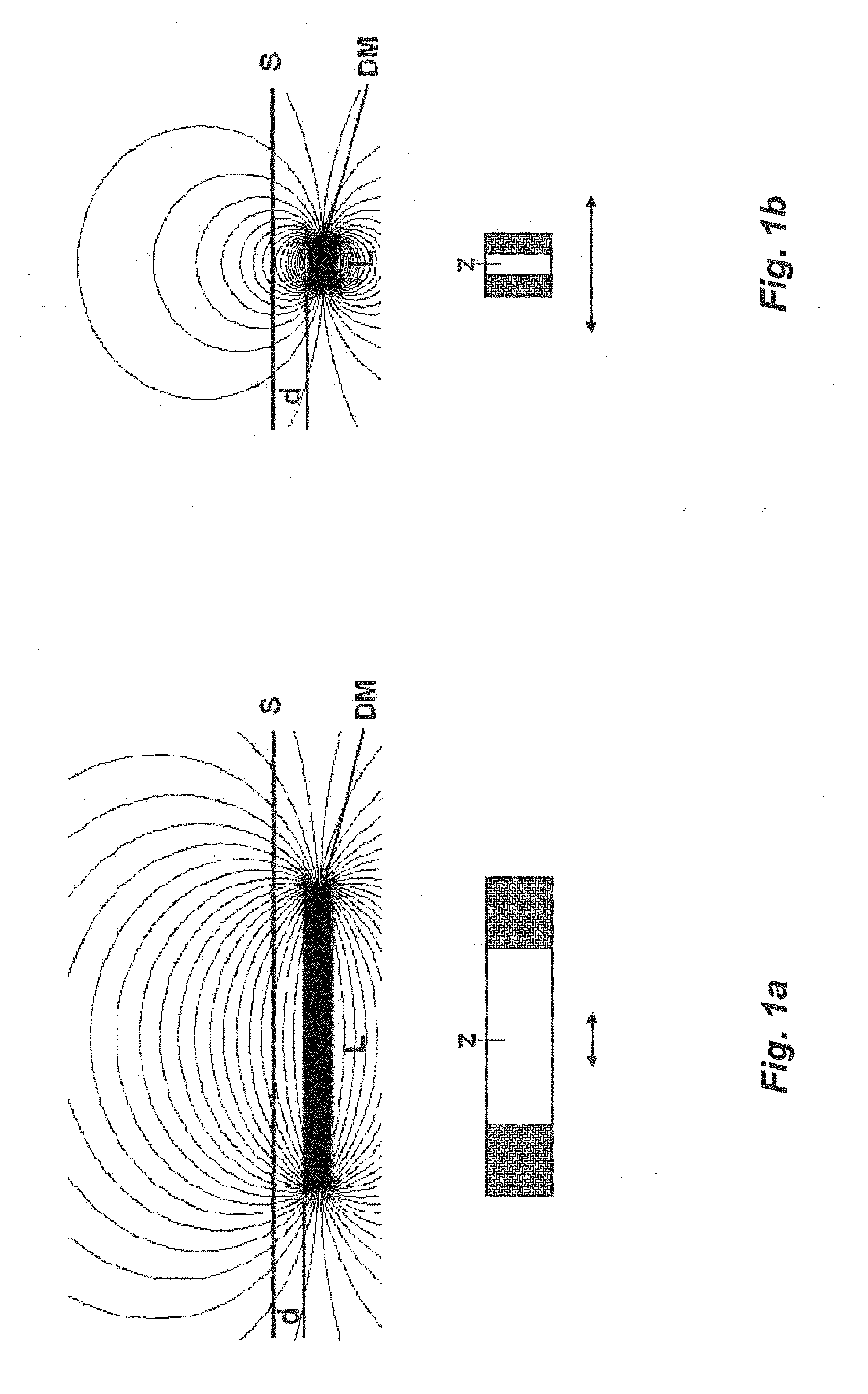
[0140]An exemplary device according to the present disclosure is composed of:[0141]a polymeric holder with a convex upper surface (50×50 mm), cylindrically curved about an axis D2 (surface curvature diameter: 275 mm), the lower surface of the holder being flat and the maximum thickness of the holder in its center measuring 2.7 mm;[0142]a grouped dipole magnet DM (30×30×6 mm), magnetized through the 30-mm thickness, located in contact with the flat lower surface of the holder, the axis of magnetization of the dipole magnet DM being along a direction D1 parallel to the lower surface of said holder and perpendicular to the cylindrical axis D2 of the curved upper surface of the holder;[0143]a flexible composite magnetic plate MP2 (NdFeB in polymeric binder; 40×40 mm, thickness 1.5 mm) located on top of and parallel to said convex upper convex surface of said polymeric holder, said magnetic plate MP2 being magnetized though its thickness with a succession of alternating N and S magnetic ...

example 2

[0147]The device described in example 1 is modified by rotating the grouped dipole magnet DM about its major axis normal to the surface so as to form an angle of +45° between D3 and D2, and an angle of −45° with D1, and the surface of the magnetic supporting plate SP was engraved with the image of a seahorse (engraving depth: 0.5 mm).

[0148]A solid rectangular area (17×27 mm) surrounded with two decorative borders was printed on the obverse surface of a paper substrate using a silkscreen UV-curing coating composition according to WO 2007 / 131833 A1. The imprinted paper substrate was brought into contact with the modified device of Example 2 while the ink was still “wet”, with the reverse of the substrate facing the surface of the supporting plate (SP). Contact was maintained between the imprinted paper and the device for about 1 second to allow for the orientation of the magnetic particles contained in the printed coating composition. The substrate carrying the oriented coating compos...


PUM


Abstract

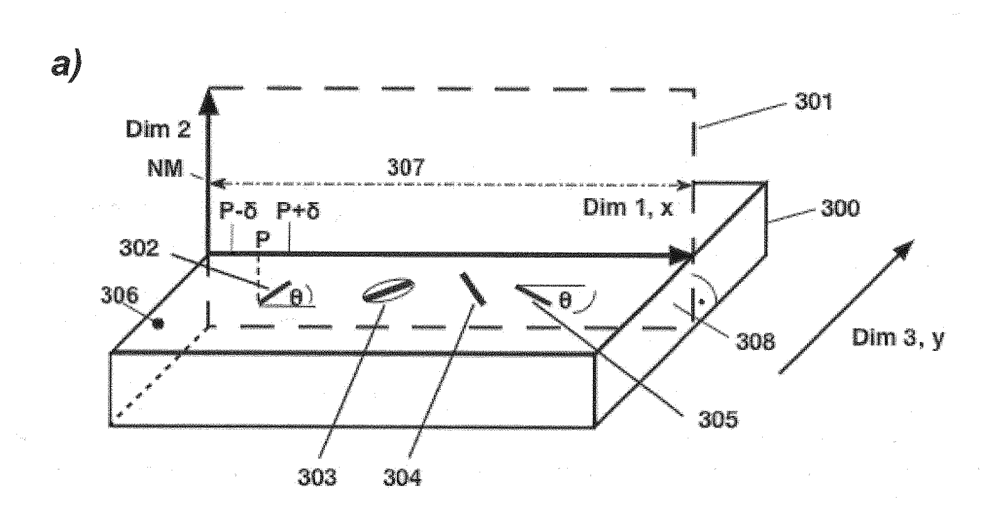
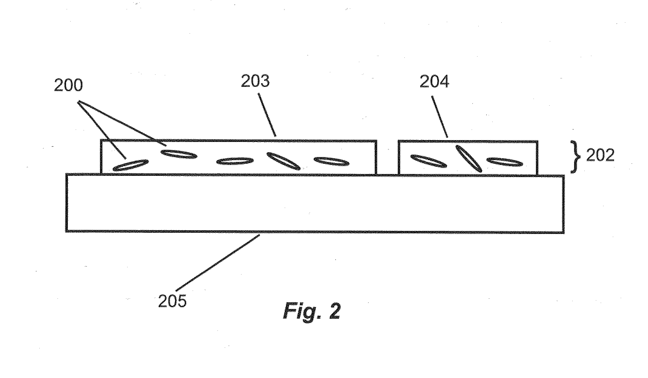
The disclosure relates to the field of graphical elements and is directed to an optical effect layer (OEL), a device and a method for producing same. The disclosure provides an optical effect that is easy to detect as such and exhibits a viewing-angle dependent apparent motion of image features over an extended length if the viewing angle with respect to the OEL changes. An OEL includes a binder material being at least partially transparent and a plurality of particles dispersed within the layer. Each particle has a non-isotropic reflectivity and may be magnetic or magnetizable. The orientation of the particles forms an orientation pattern extending over a length within an extended surface of the OEL, such that the local average of an angle between (i) a straight line along an observed longest dimension within the corresponding cross-section shape, and (ii) said first direction x varies according to a function (θ) of a position (P) along said first direction.

Description

CROSS-REFERENCE TO RELATED APPLICATIONS[0001]The present application is a U.S. National Stage of International Application No. PCT / EP2013 / 058986, filed Apr. 30, 2013, which published as WO 2013 / 167425A1 on Nov. 14, 2013, the disclosure of which is expressly incorporated by reference herein in its entirety. Further, this application claims priority under 35 U.S.C. §119 and §365 of European Application No. 12003551.4, filed May 7, 2012.FIELD OF THE DISCLOSURE[0002]The present disclosure relates to the field of graphical elements and is directed to an optical effect layer showing a viewing-angle dependent optical effect and a device and a method for producing the optical effect layer. In particular, one application of the optical effect layer is in the field of security elements for the protection of banknotes, passports and other documents, and for brand-protection. In addition or alternatively the optical effect layer may also be used for decorative purposes.BACKGROUND OF THE DISCLOS...

Claims


Application Information

Patent Timeline
IPC IPC(8): G02B5/08B42D25/40B42D25/30G02F1/00G02F1/21
CPCG02B5/08G02F1/0036G02F1/21B42D25/30B42D25/40G02F2001/213B42D2033/16B42D2033/18B42D2035/20B42D2033/20B05D3/20B05D5/065G02B5/0257B42D25/29C09D11/037G02F1/09B42D25/369B42D25/378B42D25/41B05D5/06B42D25/20B42D25/00G02F1/094G02F1/213B42D25/24B41M3/14
Inventor DEGOTT, PIERRESCHMID, MATHIEUDESPLAND, CLAUDE ALAINAMERASINGHE, CÉDRIC
Owner SICPA HLDG SA
Why Eureka
Try Eureka