
Continuously variable valve timing device

Inactive Publication Date: 2015-05-14
HYUNDAI MOTOR CO LTD +1
View PDF1 Cites 1 Cited by
  • Summary
  • Abstract
  • Description
  • Claims
  • Application Information

AI Technical Summary

Benefits of technology

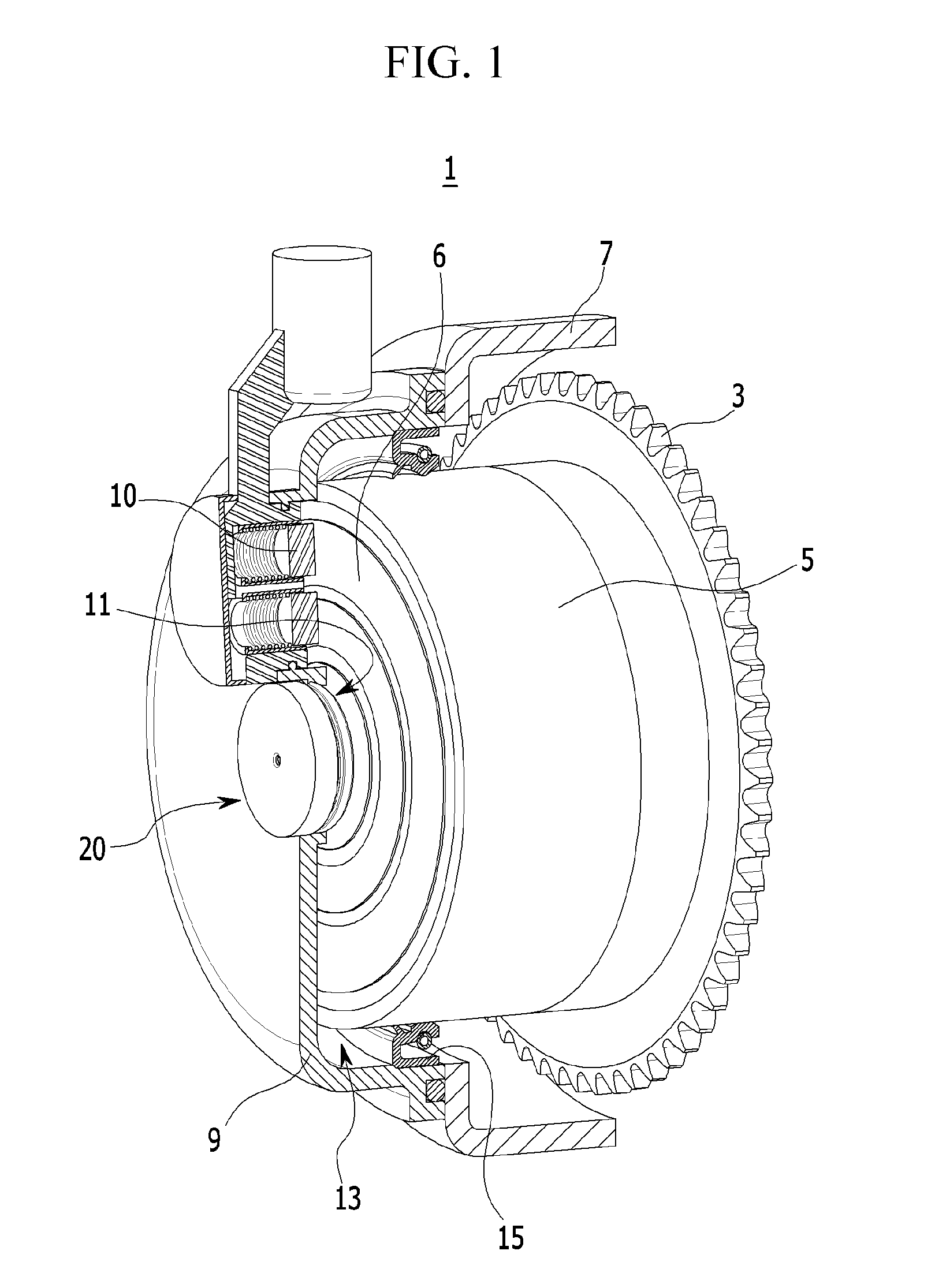
The present invention is a device that prevents oil from leaking into the internal space of an electric valve timing mechanism cover using a pressure maintaining device. This device maintains pressure in the internal space of the mechanism cover to preserve the function and durability of a seal ring, which prevents foreign substances such as moisture and dust from entering the system. This improves the operational reliability of the electric valve timing mechanism and prevents malfunctions.

Problems solved by technology

However, in the aforementioned continuously variable valve timing device in the related art, pressure in the internal space of the electric variable valve timing mechanism cover may be varied due to a variation in temperature of the engine and due to an oil seal structure that seals a contact portion of a rotating body, a seal line of the seal ring may be damaged when pressure increases due to the variation in pressure, durability such as an increase in frictional force of the oil seal may occur pressure is reduced, oil may flow from the engine side through a gap in the damaged seal ring, and as a result, a malfunction may occur on the motor that drives the electric variable valve timing mechanism.

Method used


Image

  • Continuously variable valve timing device
  • Continuously variable valve timing device
  • Continuously variable valve timing device

Examples


Embodiment Construction

[0019]It is understood that the term “vehicle” or “vehicular” or other similar term as used herein is inclusive of motor vehicles in general such as passenger automobiles including sports utility vehicles (SUV), buses, trucks, various commercial vehicles, watercraft including a variety of boats and ships, aircraft, and the like, and includes hybrid vehicles, electric vehicles, plug-in hybrid electric vehicles, hydrogen-powered vehicles and other alternative fuel vehicles (e.g. fuels derived from resources other than petroleum). As referred to herein, a hybrid vehicle is a vehicle that has two or more sources of power, for example both gasoline-powered and electric-powered vehicles.

[0020]The terminology used herein is for the purpose of describing particular embodiments only and is not intended to be limiting of the invention. As used herein, the singular forms “a”, “an” and “the” are intended to include the plural forms as well, unless the context clearly indicates otherwise. It wil...


PUM


Abstract

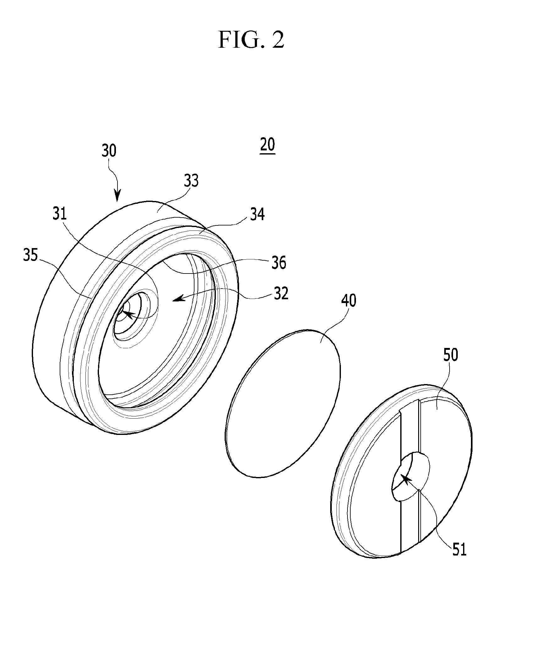
A continuously variable valve timing device is provided and includes a cam sprocket connected with a camshaft having a plurality of cams to rotate the camshaft and an electric variable valve timing mechanism connected with the cam sprocket, and driven by an electric motor. A chain cover protects the cam sprocket and a chain system from foreign substances and an electric variable valve timing mechanism cover protects the electric variable valve timing mechanism from foreign substances. A seal ring partitions an internal space between the electric variable valve timing mechanism and the electric variable valve timing mechanism cover. In addition, a pressure maintaining device is mounted within the electric variable valve timing mechanism cover to maintain pressure formed within the internal space of the electric variable valve timing mechanism cover at about atmospheric pressure.

Description

CROSS-REFERENCE TO RELATED APPLICATION[0001]The present application claims priority of Korean Patent Application Number 10-2013-0137066 filed on Nov. 12, 2013, the entire contents of which application are incorporated herein for all purposes by this reference.BACKGROUND[0002](a) Field of Invention[0003]The present invention relates to a continuously variable valve timing device, and more particularly, to a continuously variable valve timing device that maintains internal pressure of an electric variable valve timing mechanism cover partitioned by a seal ring, at atmospheric pressure to preserve function and durability of the seal ring, and prevent malfunction of an electricity driven motor.[0004](b) Description of Related Art[0005]In general, an internal combustion engine is an apparatus that generates power by suctioning air and fuel from the exterior of a vehicle, and combusting fuel in a combustion chamber, and has an intake valve configured to suction air and fuel into the combu...

Claims


Application Information

Patent Timeline
IPC IPC(8): F01L1/344
CPCF01L1/344F01L2250/02F01L2820/032F01L2301/00F01L1/34
Inventor LEE, SEUNG WOOKANG, HYUNJINKIM, JAE-CHUNBAEK, HONG KILKIM, GANG IL
Owner HYUNDAI MOTOR CO LTD
Learn More