
Seismic Image Dip Decomposition Estimation and Recomposition

a dip decomposition and seismic image technology, applied in seismicity, instruments, measurement devices, etc., can solve the problems of migration artifacts such as migration swing or smile, insufficient stacking of shot images, and difficulty in applying popular post-processing methods such as muting and residual move-out, to wave equation based migrations such as one-way wave equation migration and reverse time migration. , to achieve the effect of enhancing signals and removing nois

Active Publication Date: 2015-05-07
EXXONMOBIL UPSTREAM RES CO
View PDF3 Cites 25 Cited by
  • Summary
  • Abstract
  • Description
  • Claims
  • Application Information

AI Technical Summary

Benefits of technology

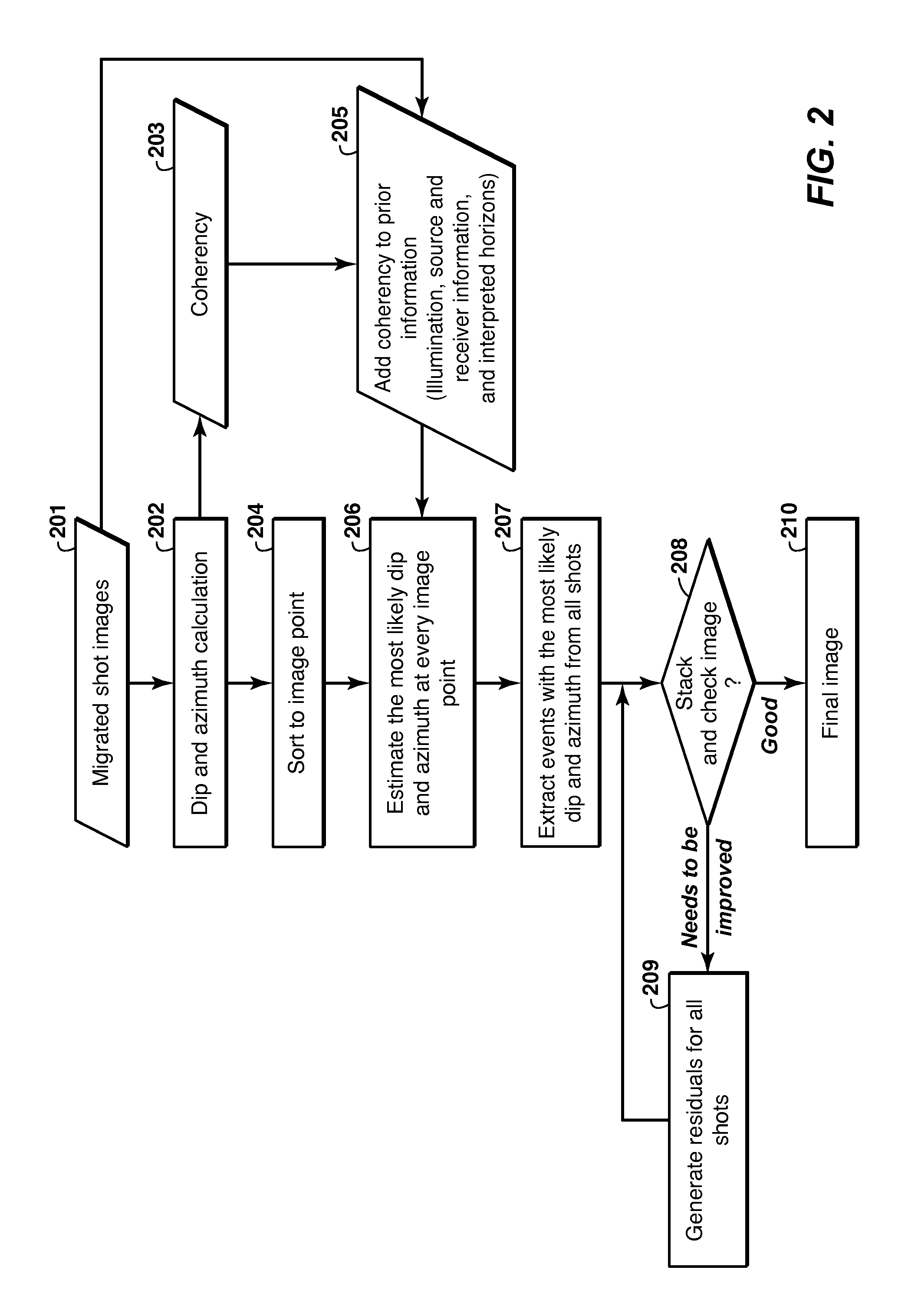
The invention is a computer-based method to improve the quality of seismic images by removing noise and enhancing signals. It involves obtaining multiple images, calculating dip information, estimating dominant dips, extracting dominant events, and stacking the events from each image. The technical effects of this method include improved image quality, reduced noise, and improved signal-to-noise ratios.

Problems solved by technology

This principle migrates seismic events to their correct locations, but it also causes migration artifacts (known as migration swing or smile) because of the limited source and receiver coverage in a shot gather.
In a region of complex geologic structure like subsalt, stacking the shot images is not enough to cancel out the migration artifacts because of spatially varying illumination caused by complex overburdens and structures.
Because of its nature of shot-by-shot implementation, it is difficult to apply two popular post-processing methods (muting and residual move-out) to wave equation based migrations such as one-way wave equation migration and reverse time migration.
However, the calculation of the angle gathers at each image point for each shot gather often is very computationally expensive.
However, these methods reduce the amount of input data for stacking substantially by the forming of partial or sub-stacks, where valuable information in individual images could be rendered invisible.
In particular, local dips that may be separated on a shot-by-shot basis may be combined by partial stacking, reducing the effectiveness of dip-estimation methods in the area.
Amplitude information might not be preserved very well during the final stacking process with the different weights of each partial stack.

Method used


Image

  • Seismic Image Dip Decomposition Estimation and Recomposition
  • Seismic Image Dip Decomposition Estimation and Recomposition
  • Seismic Image Dip Decomposition Estimation and Recomposition

Examples


examples

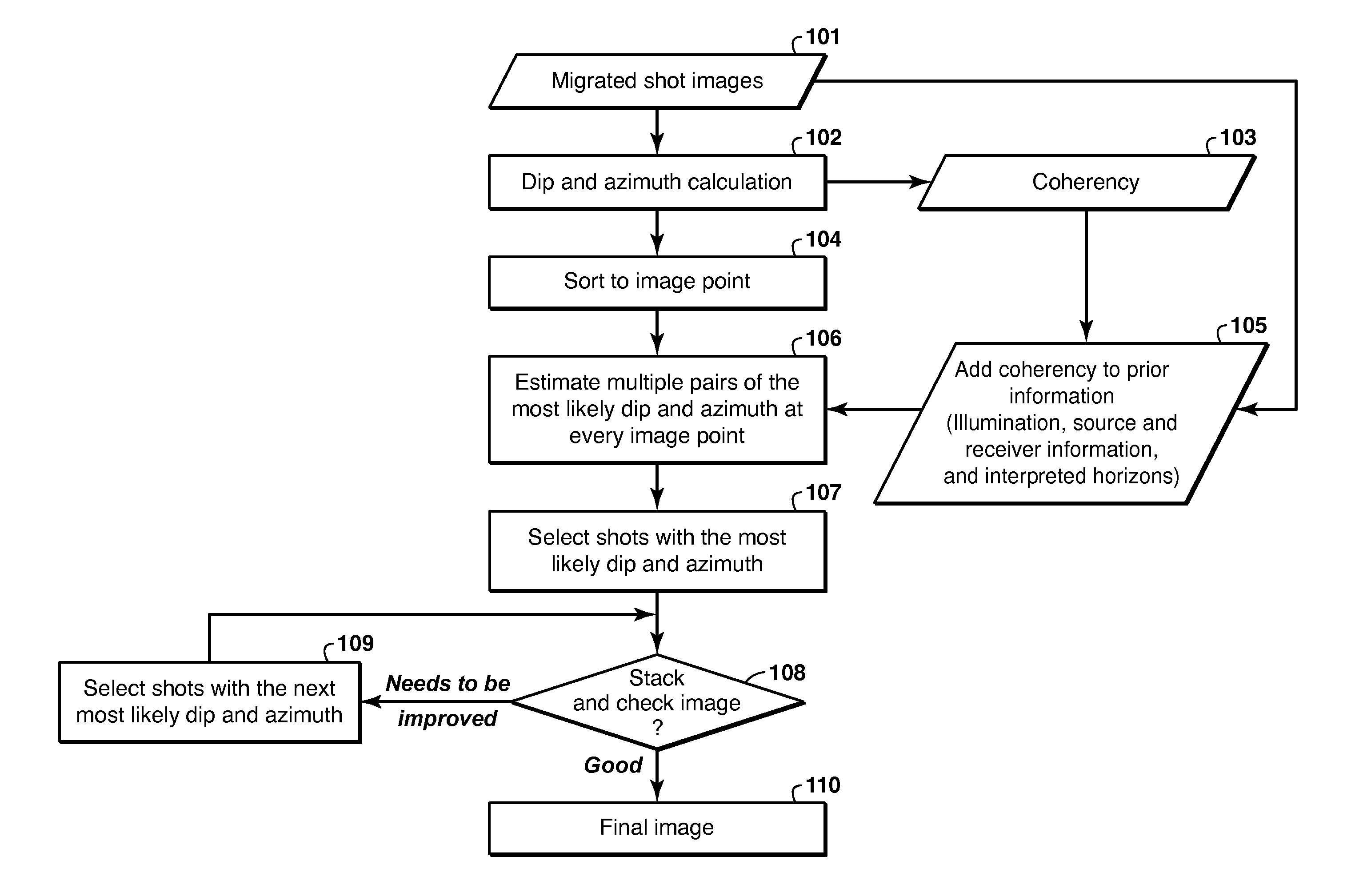
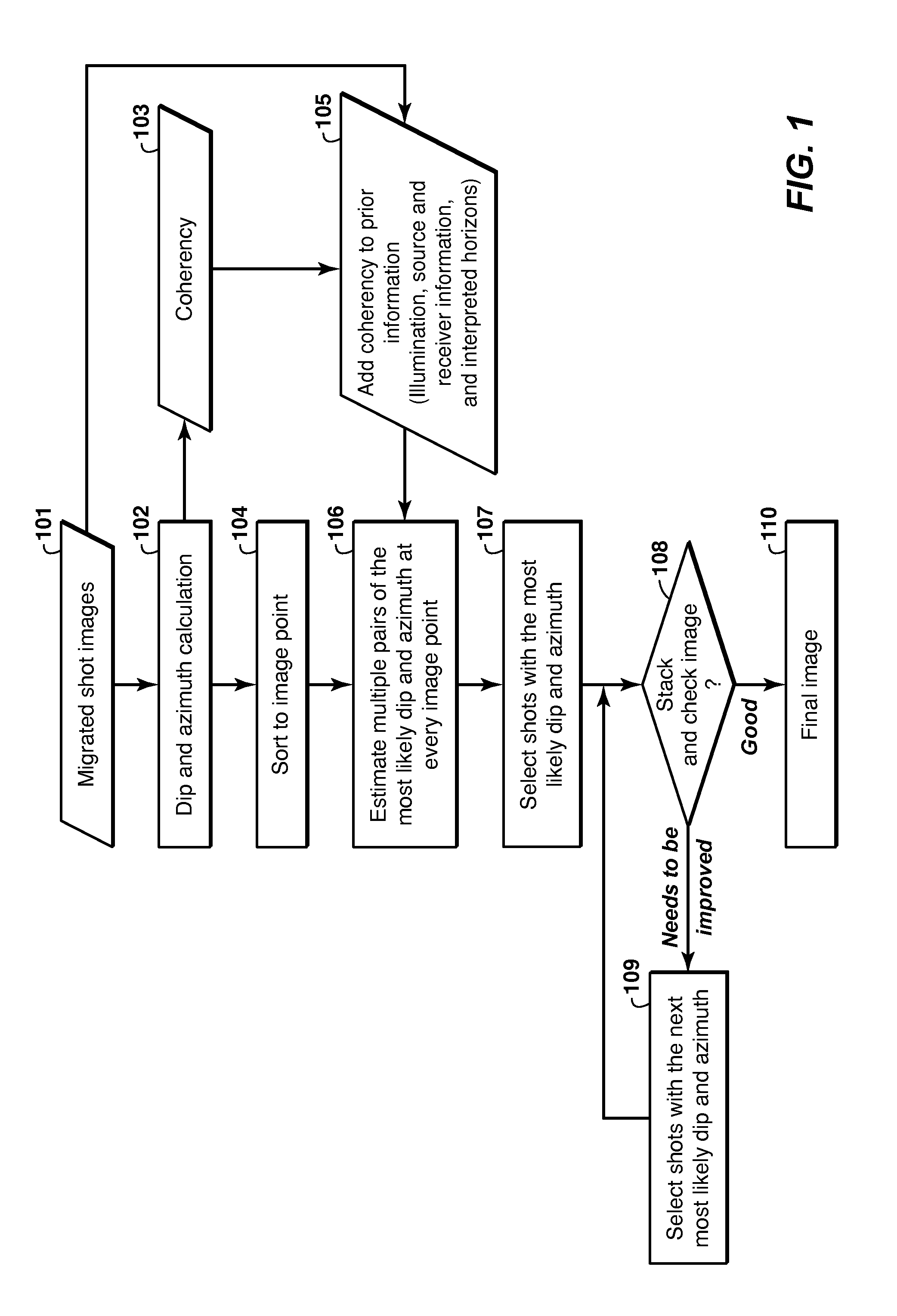
[0033]The embodiment of FIG. 1 was tested on a two-dimensional example. FIG. 3 shows a P-wave velocity model for synthetic data generation and reverse time migration. P-wave velocity increases with depth in sediment layers and 301 is a salt body of high velocity. In the sediment layer, lateral variation is very mild. FIG. 4 is a reverse time migration image (a conventional stacked image) for the model shown in FIG. 3, where no post-processing was applied before stacking. 401, 402 and 403 indicate unwanted noises generated by reverse time migration because of two major reasons in this synthetic example: variable or uneven illumination of acquisition geometry, and acoustic approximation of the elastic wavefield. The original velocity model shown in FIG. 3 does not have steep dip events in sediment layers in FIG. 4 indicated by 401, 402 and 403, which means that 401, 402 and 403 should be treated as noises and removed in a proper way before stacking.

[0034]FIG. 5 shows a result of step ...


PUM


Abstract

Method for optimal stacking of seismic images to remove noise and enhance signals in seismic images (101) outputted from a Reverse Time Migration (RTM) imaging process. Dip information is calculated (102) and then sorted by image point (104), for each seismic image to be stacked. A dominant dip and azimuth is determined at each image point (106), and only those events are stacked (107). If the image is still noisy or lacking in detail (108), the process may be iterated (109) to improve the selection of most likely dip and azimuth.

Description

CROSS-REFERENCE TO RELATED APPLICATION[0001]This application claims the benefit of U.S. Provisional Patent Application 61 / 900,109, filed Nov. 5, 2013, entitled SEISMIC IMAGE DIP DECOMPOSITION ESTIMATION AND RECOMPOSITION, the entirety of which is incorporated by reference herein.FIELD OF THE INVENTION[0002]This disclosure relates generally to the field of geophysical prospecting for hydrocarbons and, more particularly, the seismic data processing. Specifically, the disclosure relates to optimal stacking of shot images outputted from a Reverse Time Migration (RTM) imaging process, to remove noise and enhance RTM images.BACKGROUND OF THE INVENTION[0003]Migration is a common and essential technique for processing shot gathers of seismic data acquired in the field to produce a subsurface image with reflectors at their correct locations. There are various migration methods to produce a subsurface image such as Kirchhoff migration, beam migration, one-way wave equation migration, and reve...

Claims


Application Information

Patent Timeline
IPC IPC(8): G01V1/36G01V1/34
CPCG01V1/362G01V2210/74G01V2210/322G01V1/345G01V2210/512G01V2210/522
Inventor CHA, YOUNG HOCURRY, WILLIAM
Owner EXXONMOBIL UPSTREAM RES CO
Learn More