Multi-speed gearbox

a gearbox and multi-speed technology, applied in mechanical equipment, transportation and packaging, gearing, etc., can solve the problems of significant hydraulic losses, and achieve the effects of improving efficiency, simplifying design, and optimizing component load and installation siz

Active Publication Date: 2015-04-30
ZF FRIEDRICHSHAFEN AG
View PDF1 Cites 6 Cited by
  • Summary
  • Abstract
  • Description
  • Claims
  • Application Information

AI Technical Summary

Benefits of technology

The present invention proposes a multi-stage transmission that has optimum design and efficiency. It has a low number of shift elements, making it easy to access and actuate upon demand. The transmission ratios are suitable for passenger vehicles and result in improved driving comfort and reduced fuel consumption. The design complexity and component load of the transmission are minimized. The multi-stage transmission can be used for both frontal transverse and standard designs. It reduces wear, utilizes low torudes, and requires less installation space and costs.

Problems solved by technology

According to the prior art, the shift elements of multi-stage transmission thus designed, which are usually designed as lamellar clutches or brakes, are actuated hydraulically, which disadvantageously results in significant hydraulic losses.

Method used


Image

  • Multi-speed gearbox
  • Multi-speed gearbox

Examples


Embodiment Construction

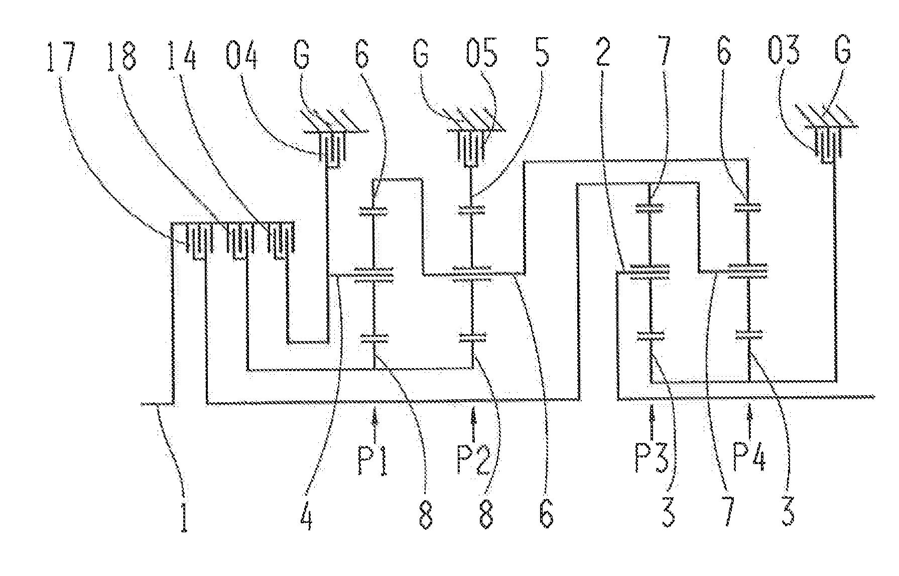
[0032]FIG. 1 shows a multi-stage transmission, according to the invention, which has a drive shaft 1, an output shaft 2, and four planetary gear sets P1, P2, P3 and P4 which are disposed in a housing G. In the example shown in FIG. 1, planetary gear sets P1, P2, P3 P4 are designed as minus planetary gear sets. According to the invention, at least one of the planetary gear sets P1, P2, P3, P4 can be implemented as a plus planetary gear set if the carrier and ring gear connection are exchanged and, simultaneously, the value of the stationary transmission ratio is increased by 1 in comparison to the embodiment as a minus planetary gear set.

[0033]In the embodiment shown here, viewed axially, the planetary gear sets P1, P2, P3, P4 are disposed in the sequence of the first planetary gear set P1, the second planetary gear set P2, the third planetary gear set P3, the fourth planetary gear set P4. According to the invention, the axial sequence of the individual planetary gear sets and the co...


PUM


Abstract

Multi-stage transmission comprising four planetary gear sets, eight rotatable shafts and six shift elements. Sun of first set is connected to eighth shaft connected to sun of second set and is connectable, via third clutch, to drive shaft. Drive shaft is connectable, via first clutch, to fourth shaft connected to carrier of first set and is couplable, via second brake, to housing. Drive shaft is connectable, via second clutch, to seventh shaft connected to carrier of fourth set and ring of third set, Sixth shaft is connected to ring of first set, carrier of second set and ring of fourth planetary gear set. Third shaft is connected to sun of third set and sun of fourth set and is couplable, via first brake, to housing. Fifth shaft is connected to ring of second set and is couplable, via third brake, to housing. Output shaft is connected to carrier of third set.

Description

[0001]This application is a National Stage completion of PCT / EP2013 / 055071 filed Mar. 13, 2013, which claims priority from German patent application serial no. 10 2012 206 817.1 filed Apr. 25, 2012.FIELD OF THE INVENTION[0002]The present invention relates to a multi-stage transmission of a planetary design, in particular an automatic transmission for a motor vehicle.BACKGROUND OF THE INVENTION[0003]According to the prior art, automatic transmissions, particularly for motor vehicles, comprise planetary gear sets that are shifted using friction elements or shift elements such as clutches and brakes, and typically are connected to a start-up element, such as a hydrodynamic torque converter or a fluid coupling, that is subject to a slip effect and is provided optionally with a lock-up clutch.[0004]Such an automatic transmission is known, for example, from DE 199 12 480 B4 by the applicant. It comprises three single-carrier planetary gear sets, as well as three brakes and two clutches fo...

Claims


Application Information

Patent Timeline
IPC IPC(8): F16H3/66
CPCF16H3/66F16H2003/445F16H2200/2046F16H2200/0082F16H2200/2012F16H2200/0065F16H3/663F16H2200/2094
Inventor BECK, STEFANSIBLA, CHRISTIANRIEGER, WOLFGANG
Owner ZF FRIEDRICHSHAFEN AG
Why Eureka
Try Eureka