Method and apparatus for handling material in a pneumatic materials handling system

a technology of pneumatic material handling and material handling, which is applied in the field of material handling systems, can solve the problems of high energy consumption of drive devices and drive devices, affecting the operation of rotary shapers, and reducing so as to prevent or at least reduce the load acting on the handling means, and reduce the susceptibility to clogging

Active Publication Date: 2015-04-30
MARICAP OY
View PDF35 Cites 2 Cited by
  • Summary
  • Abstract
  • Description
  • Claims
  • Application Information

AI Technical Summary

Benefits of technology

[0014]The solution according to the invention has a number of important advantages. By means of the invention a particularly efficient solution for the handling, more particularly for the pneumatic pipe transport, of material is achieved. With the solution according to the invention, the infeed of material to be handled can be adjusted in the feeder channel before the rotary shaper, in this case with the arresting means the weight effect produced by the material to be handled on the rotary shaper, more particularly the load acting on its handling means, can be prevented or at least reduced. In this case the power requirement of the rotary shaper is smaller. In addition, the susceptibility to clogging decreases. With the arresting means the infeed of material in the feeder channel can also be boosted. According to one method of use, the arresting means is in the feeder channel when the rotating handling means of the rotary shaper rotate in a first direction, and the arresting means is not in the feeder channel when the handling means of the rotary shaper rotate in a second direction. This is an effective solution particularly for large quantities of waste and for heavy waste sacks. With the solution according to the invention, waste material can be efficiently fed to the rotary shaper and compacted with the rotary shaper, and efficient transportation can be achieved with a significantly smaller pipe size compared to unshaped waste material. By using suction, in addition to gravity, to convey the material to be handled from the rotary shaper into the transport pipe, an advantageous solution for a combination of a rotary shaper and pipe transport is achieved.

Problems solved by technology

In the solution according to the publication high operating powers are typically needed, especially in situations in which the device is used to cut or fine-grind a material, in which case the energy consumption of the drive devices and the costs of the drive devices are high.
In addition, the passage of stones or other corresponding material between the cutting blades can cause breakage of the blades.
This requires significant driving force from the drive device of the rotary shaper or it can also slow down the operation of the rotary shaper.

Method used


Image

  • Method and apparatus for handling material in a pneumatic materials handling system
  • Method and apparatus for handling material in a pneumatic materials handling system

Examples


Embodiment Construction

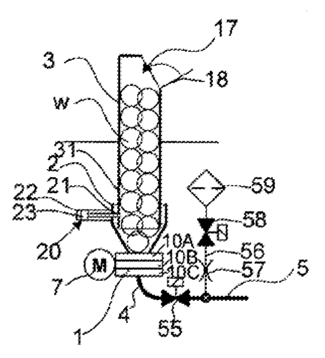
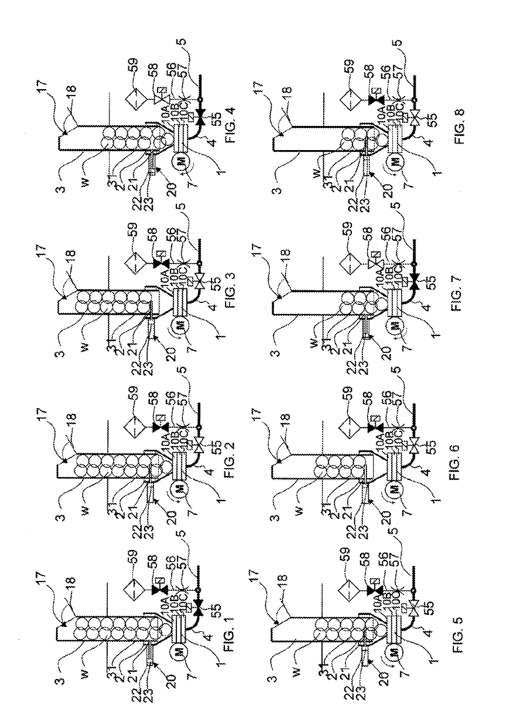
[0017]FIGS. 1-8 present as a simplified diagram one embodiment of the solution according to the invention, in which the rotary shaper device 1 is arranged in connection with a feeder channel, such as a feeder chute, refuse chute or corresponding, with a fitting part 2, which in the figure is conical. The feeder channel is e.g. a tubular part, inside the wall 31 of which remains space for material. The material w, such as household waste, waste paper, cardboard or other waste, is fed e.g. from an input aperture 17 into the feeder channel 3 and from there onwards, via the fitting part 2, into a rotary shaper 1. An openable and closable hatch 18, which is open in the situation of the figure, is in connection with the input aperture in FIG. 1. The material w to be handled is shaped and compacted in the rotary shaper and after handling is conducted via an output coupling 4 into conveying piping 5 by means of the suction and / or a pressure difference produced by e.g. the drive devices (not...


PUM


Abstract

Method for feeding material into a shaping device in a pneumatic materials conveying system, in which method material, such as waste material is fed into a shaping device, and/or through it, in a feeder channel by the aid of at least partly gravity and at least partly suction and/or a pressure difference, which shaping device is a rotary shaper, with which the material is processed so as to be denser and is conveyed onwards. In the material infeed direction before the rotary shaper is a movable arresting device, which arresting device has a first position, in which it extends into the feeder channel and in which first position the arresting device receives at least some of the force effect produced by the material in the feeder channel and in which the transfer of the material in the feeder channel is limited, if necessary, with the arresting device, and which arresting device has a second position, in which the arresting device does not extend into the feeder channel.

Description

BACKGROUND OF THE INVENTION[0001]The object of the invention is a method as defined in the preamble of claim 1.[0002]Another object of the invention is an apparatus as defined in the preamble of claim 11.[0003]The invention relates generally to materials handling systems, such as partial-vacuum conveying systems, more particularly to the collection and conveying of wastes, such as to the conveying of household wastes.[0004]Systems wherein wastes are conveyed in piping by means of an air current produced by a pressure difference or suction are known in the art. In these, wastes are conveyed long distances in the piping. It is typical to these systems that a partial-vacuum apparatus is used to achieve a pressure difference, in which apparatus a partial vacuum is achieved in the conveying pipe with partial-vacuum generators, such as with vacuum pumps or with an ejector apparatus. A conveying pipe typically comprises at least one valve means, by opening and closing which the replacement...

Claims


Application Information

Patent Timeline
Patent Type & Authority Applications(United States)
IPC IPC(8): B65F5/00B65G53/24
CPCB65G53/24B65F5/005B02C23/02B65G53/40
Inventor SUNDHOLM, GORAN
Owner MARICAP OY
Why Eureka
Try Eureka