
Method of making a spectacle lens

a technology of spectacle lens and moulding method, which is applied in the field of moulding for producing spectacle lens, can solve the problems of inability to recycle this material, large blockage of the blank surface area, and high cost of heavy metal alloys used, and achieve the effect of improving the adhesion to the material

Active Publication Date: 2015-04-30
CARL ZEISS VISION INT GMBH
View PDF3 Cites 21 Cited by
  • Summary
  • Abstract
  • Description
  • Claims
  • Application Information

AI Technical Summary

Benefits of technology

The invention allows for the casting of spectacle lenses with different coatings and provides a better adhesion between the coatings and the lens material. The use of a flexible membrane as a shaping element enables precise shaping of the lens surface and compensates for changes in volume during polymerization. 3D printing can also be used to achieve some of the desired prescription powers. Overall, this invention improves the manufacturing process for spectacle lenses.

Problems solved by technology

Recycling of this material is not possible.
Only a small surface area of the blank is generally blocked, since the heavy-metal alloys used are very expensive and, what is more, very elaborate cleaning of the waste water is necessary in order to avoid contamination thereof with heavy metals.
During the machining, the protruding lens edges tend to experience undesired oscillations or to yield and fracture.
The oscillation can result in a surface having an undesired structure, and the latter cannot be polished out, since oscillation and yielding of the lens edge also occur during the polishing.
It appears doubtful whether such a method is practicable.

Method used


Image

  • Method of making a spectacle lens
  • Method of making a spectacle lens
  • Method of making a spectacle lens

Examples


Embodiment Construction

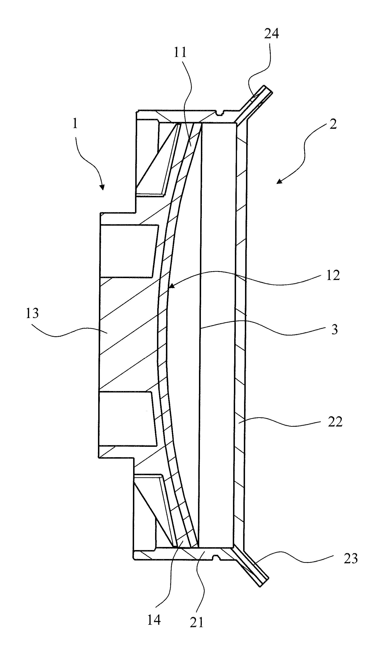
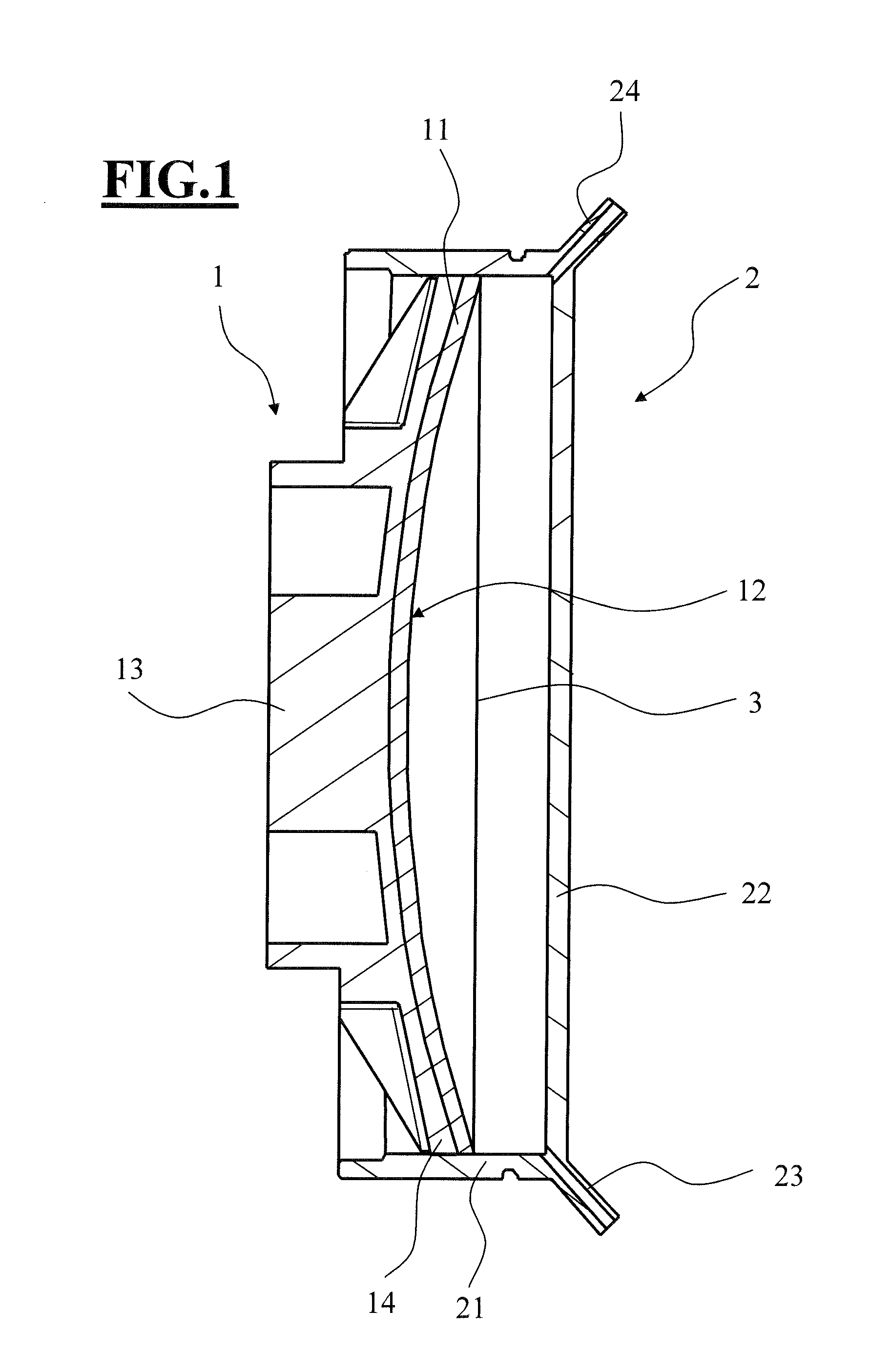
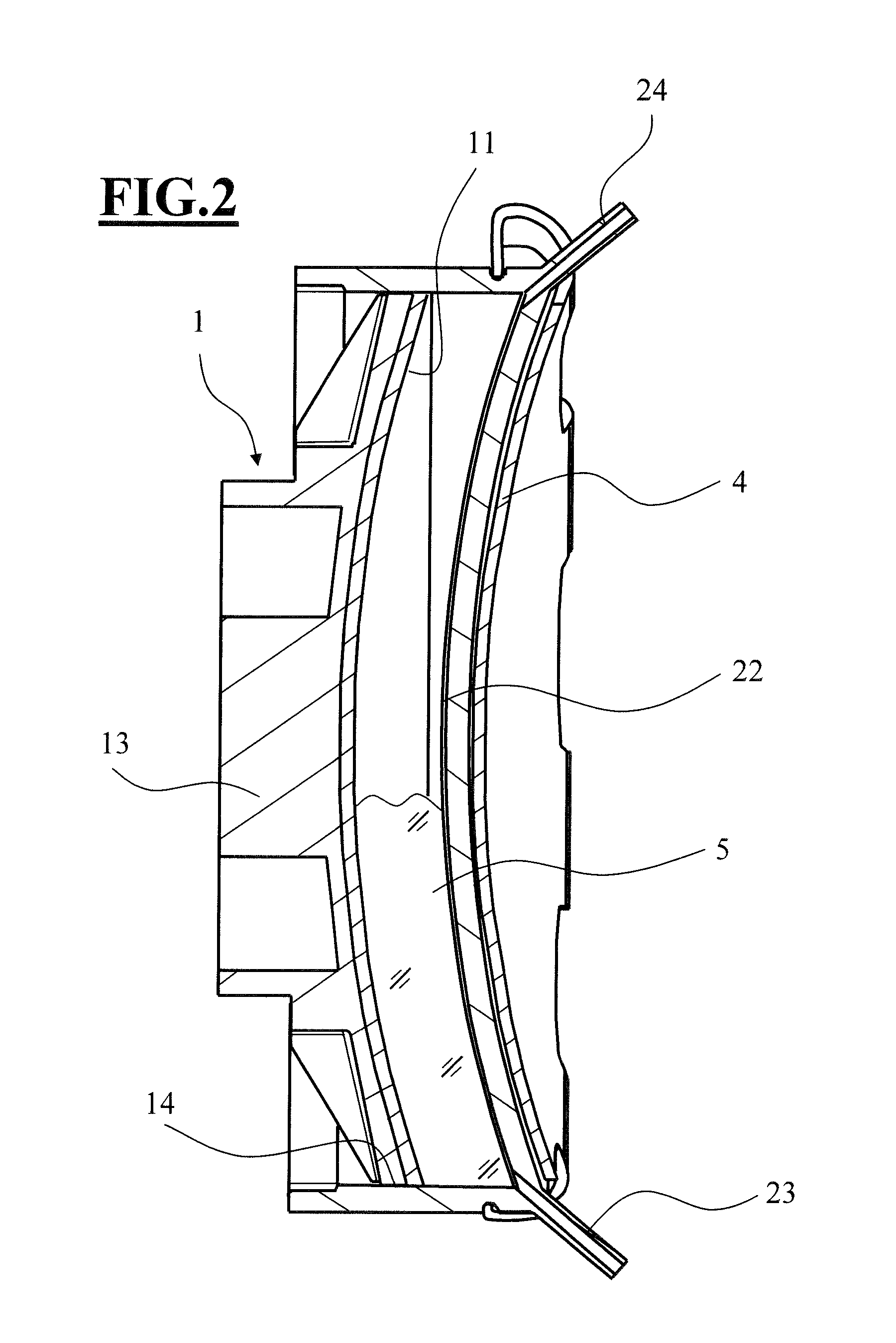
[0066]FIG. 1 shows, in cross section, a mold 1 inserted into a sealing ring 2.

[0067]The mold 1 has a mold shell 11, which has a mold surface, or optical surface 12, designed for casting a blank. In the illustrative embodiment shown, this optical surface 12 is concave; it can, for example, be a spherical surface or a rotationally symmetrical aspherical surface.

[0068]The mold 1 and in particular the mold shell 11 with the optical surface 12 are produced by 3D printing. The optical surface 12 has a shape and surface condition which, during the casting process, define a surface of a spectacle lens which, without further working, has a sufficient optical quality. By production by 3D printing, this surface can in particular be adapted individually to the intended user and, for example, can already have prescription values.

[0069]The mold 1 has a block piece 13 which serves to connect the mold 1, and a blank cast thereon, to machining tools for further working of the blank to give the finis...


PUM

PropertyMeasurementUnit
heightsaaaaaaaaaa
thicknessesaaaaaaaaaa

Abstract

A method for making a spectacle lens includes joining a mold and a sealing ring. The mold has an integrated block piece and a mold shell made by primary shaping and the sealing ring has a first end face, a second end face, a peripheral seal, an opening disposed on the first end face configured to receive a mold, and a flexible membrane on the second end face. A polymerizable material is introduced into the mold cavity with the aid of a pump action of the flexible membrane of the sealing ring. The flexible membrane of the sealing ring is fixed in a desired surface shape and the polymerization is carried out. The mold is removed with a cast-on spectacle lens blank.

Description

CROSS REFERENCE TO RELATED APPLICATION[0001]This application claims priority of German patent application no. 10 2013 222 232.7, filed Oct. 31, 2013, the entire content of which is incorporated herein by reference.FIELD OF THE INVENTION[0002]The invention relates to a mold for producing a spectacle lens, with an integrated block piece and a mold shell. The invention further relates to a sealing ring for such a mold, an arrangement made of a mold according to the invention and of a sealing ring according to the invention, a method for producing a mold according to the invention, and a method for producing spectacle lenses.BACKGROUND OF THE INVENTION[0003]In the production of a spectacle lens, a blank is generally first of all cast from a suitable plastic and, in a second manufacturing step called the prescription lens manufacture, is brought to the final shape to achieve the prescription values. The prescription lens manufacture involves work to remove material. To minimize the neces...

Claims


Application Information

Patent Timeline
Patent Type & Authority Applications(United States)
IPC IPC(8): B29D11/00B29C45/00
CPCB29D11/00009B29L2011/0016B29C45/0055B29D11/00538B29D11/00548B29C45/37B29C45/376
Inventor MESCHENMOSER, RALFKURZ, NORBERTRIEDEL, MALTEDUEWEL, STEPHAN
Owner CARL ZEISS VISION INT GMBH
Learn More