
Use of grapho-epitaxial directed self-assembly to precisely cut lines

a self-assembly and grapho-epitaxial technology, applied in the direction of photomechanical equipment, instruments, photosensitive material processing, etc., can solve the problem of limiting the density scaling of integrated circuit pattern density, the distance between two line ends, and the limit of what can be achieved optically

Active Publication Date: 2015-04-23
TOKYO ELECTRON LTD
View PDF6 Cites 26 Cited by
  • Summary
  • Abstract
  • Description
  • Claims
  • Application Information

AI Technical Summary

Benefits of technology

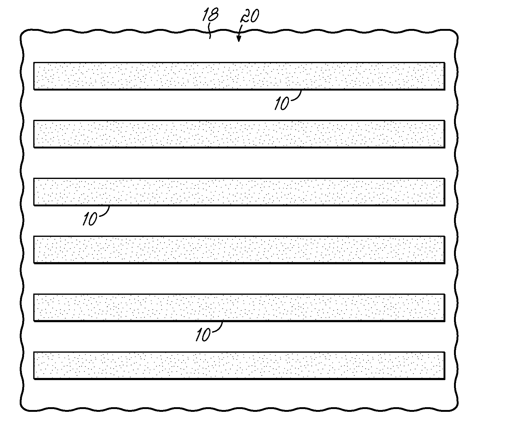
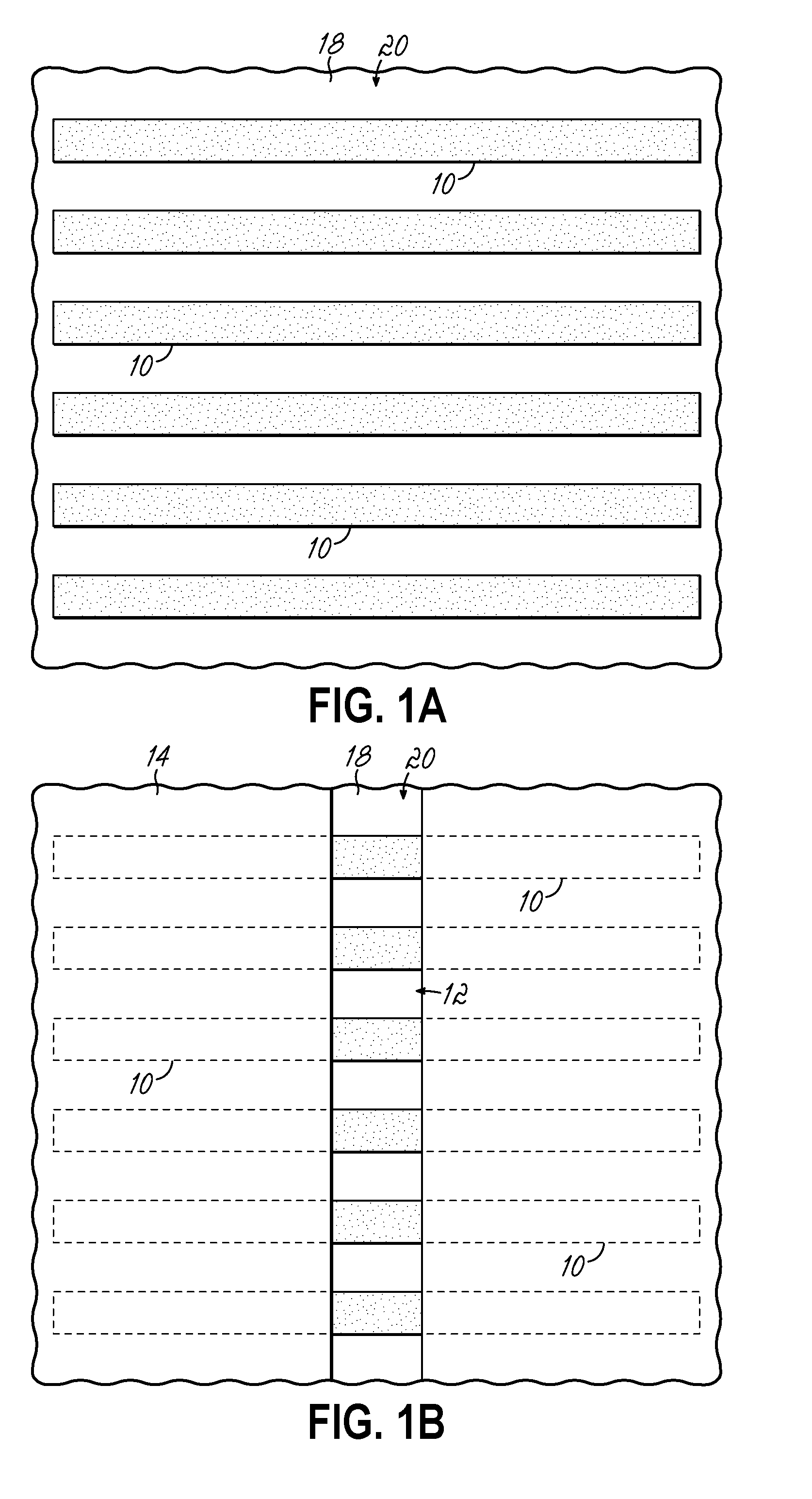
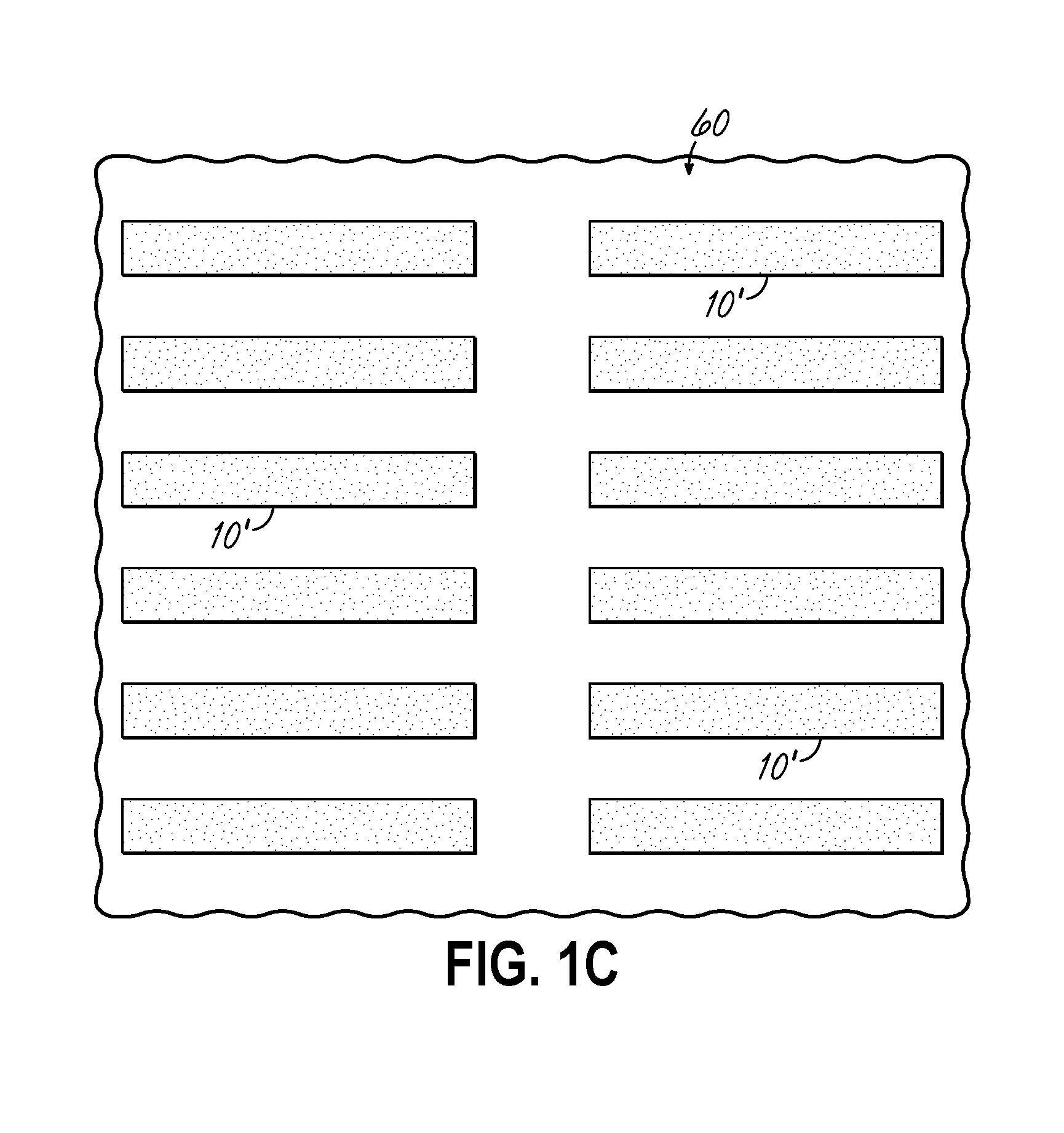
This patent describes a method for creating a patterned surface on a substrate by using a combination of layers and techniques. First, a layer of material is applied to the substrate to create lines on top. A layer of material is then applied over the lines and a layer of radiation-sensitive material is applied on top. The radiation-sensitive material is then patterned to form a pattern of exposed areas. These exposed areas are then used as a template to create a pattern of cuts in the lines. After the cuts are made, the template is removed and a second layer of radiation-sensitive material is applied over the lines and cuts to create a second set of cuts. This process results in a patterned surface with precise alignment and cuts in the lines. The use of specific block copolymers and treatments of the templates can improve the accuracy and stability of the patterned surface. The technical effects achieved by this method allow for precise patterning and alignment of lines on a substrate.

Problems solved by technology

One of the limitations on the density scaling of integrated circuit (IC) patterns is the distance between two line ends.
As we continue the path of scaling, however, the lithography of the printing of a trench pattern is reaching the limits of what can be achieved optically.
This leads to a limit for the end-to-end spacing for abutting lines, and an overall decrease in the packing density of the circuits comprising these lines.

Method used


Image

  • Use of grapho-epitaxial directed self-assembly to precisely cut lines
  • Use of grapho-epitaxial directed self-assembly to precisely cut lines
  • Use of grapho-epitaxial directed self-assembly to precisely cut lines

Examples


Embodiment Construction

[0026]Methods of designing and using grapho-epitaxy and optionally chemo-epitaxy to drive assembly of a block copolymer for patterning line features are disclosed in various embodiments. However, one skilled in the relevant art will recognize that the various embodiments may be practiced without one or more of the specific details or with other replacement and / or additional methods, materials, or components. In other instances, well-known structures, materials, or operations are not shown or described in detail to avoid obscuring aspects of various embodiments of the present invention.

[0027]Similarly, for purposes of explanation, specific numbers, materials, and configurations are set forth in order to provide a thorough understanding. Nevertheless, the embodiments of the present invention may be practiced without specific details. Furthermore, it is understood that the illustrative representations are not necessarily drawn to scale.

[0028]Reference throughout this specification to “...


PUM

PropertyMeasurementUnit
Thicknessaaaaaaaaaa
Widthaaaaaaaaaa
Dimensionaaaaaaaaaa

Abstract

A method for forming a patterned topography on a substrate is provided. The substrate is initially provided with an exposed plurality of lines formed atop. An embodiment of the method includes aligning and preparing a first directed self-assembly pattern (DSA) pattern immediately overlying the plurality of lines, and transferring the first DSA pattern to form a first set of cuts in the plurality of lines. The embodiment further includes aligning and preparing a second DSA pattern immediately overlying the plurality of lines having the first set of cuts formed therein, and transferring the second DSA pattern to form a second set of cuts in the plurality of lines. The first and second DSA patterns each comprise a block copolymer having a hexagonal close-packed (HCP) morphology and a characteristic dimension Lo that is between 0.9 and 1.1 times the spacing between individual lines of the plurality of lines.

Description

[0001]The present application claims the benefit of and priority to co-pending U.S. Provisional Patent Application Nos. 61 / 893,277 and 61 / 893,275, each filed on Oct. 20, 2013, the disclosures of which are hereby incorporated by reference herein in their entirety.FIELD OF THE INVENTION[0002]This invention relates to Directed Self-Assembly (DSA) of block copolymers (BCPs) and using them to make arrays of cut patterns in line structures.BACKGROUND OF THE INVENTION[0003]One of the limitations on the density scaling of integrated circuit (IC) patterns is the distance between two line ends. Fundamentally, this structure does not follow the same optical scaling as other features in critical circuit patterns (e.g., the critical dimension of a line). Therefore, the industry is always looking for better ways to bring line ends closer together. Starting around the 45 nm node, many IC manufacturers began a double patterning scheme where the lines were created using a first lithographic pattern,...

Claims


Application Information

Patent Timeline
IPC IPC(8): G03F7/20G03F7/30G03F7/42G03F7/16
CPCG03F7/203G03F7/16G03F7/42G03F7/30G03F7/168G03F7/0002G03F7/091G03F7/165G03F7/40H01L21/0273H01L21/0335H01L21/0337H01L21/0338H01L21/3081H01L21/3086H01L21/3088H01L21/31116H01L21/32139
Inventor SOMERVELL, MARK H.RATHSACK, BENJAMEN M.
Owner TOKYO ELECTRON LTD
Learn More