Scroll-type compressor

a compressor and scroll technology, applied in the direction of machines/engines, rotary/oscillating piston pump components, liquid fuel engines, etc., can solve problems such as noise and vibration, and achieve the effects of suppressing repeated contact and separation, suppressing collision of orbiting scrolls, and high pressur

Active Publication Date: 2015-04-16
TOYOTA IND CORP
View PDF8 Cites 11 Cited by
  • Summary
  • Abstract
  • Description
  • Claims
  • Application Information

AI Technical Summary

Benefits of technology

[0005]In view of the above aspects, the present specification aims at providing a scroll-type compressor that can be operated silently.
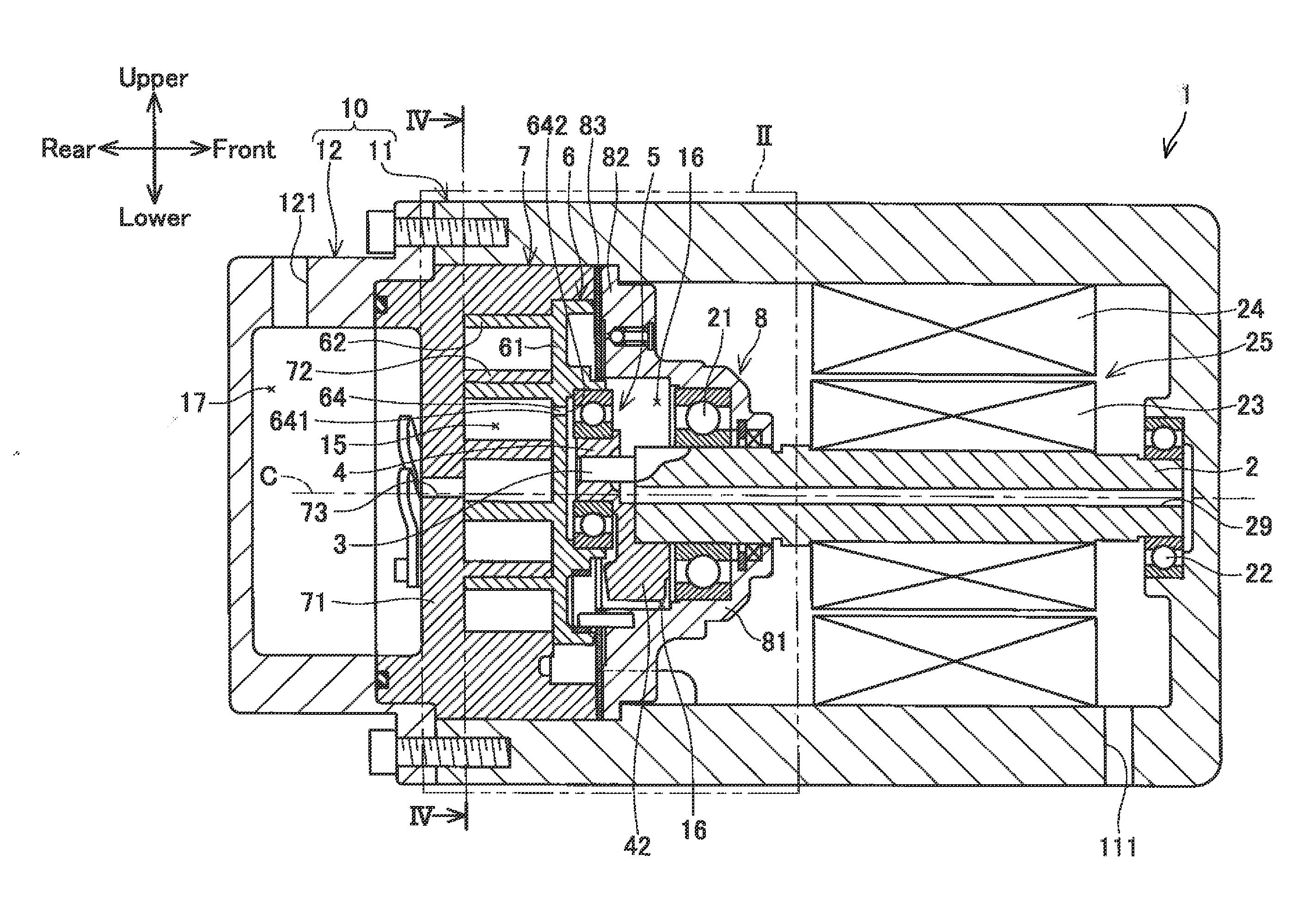
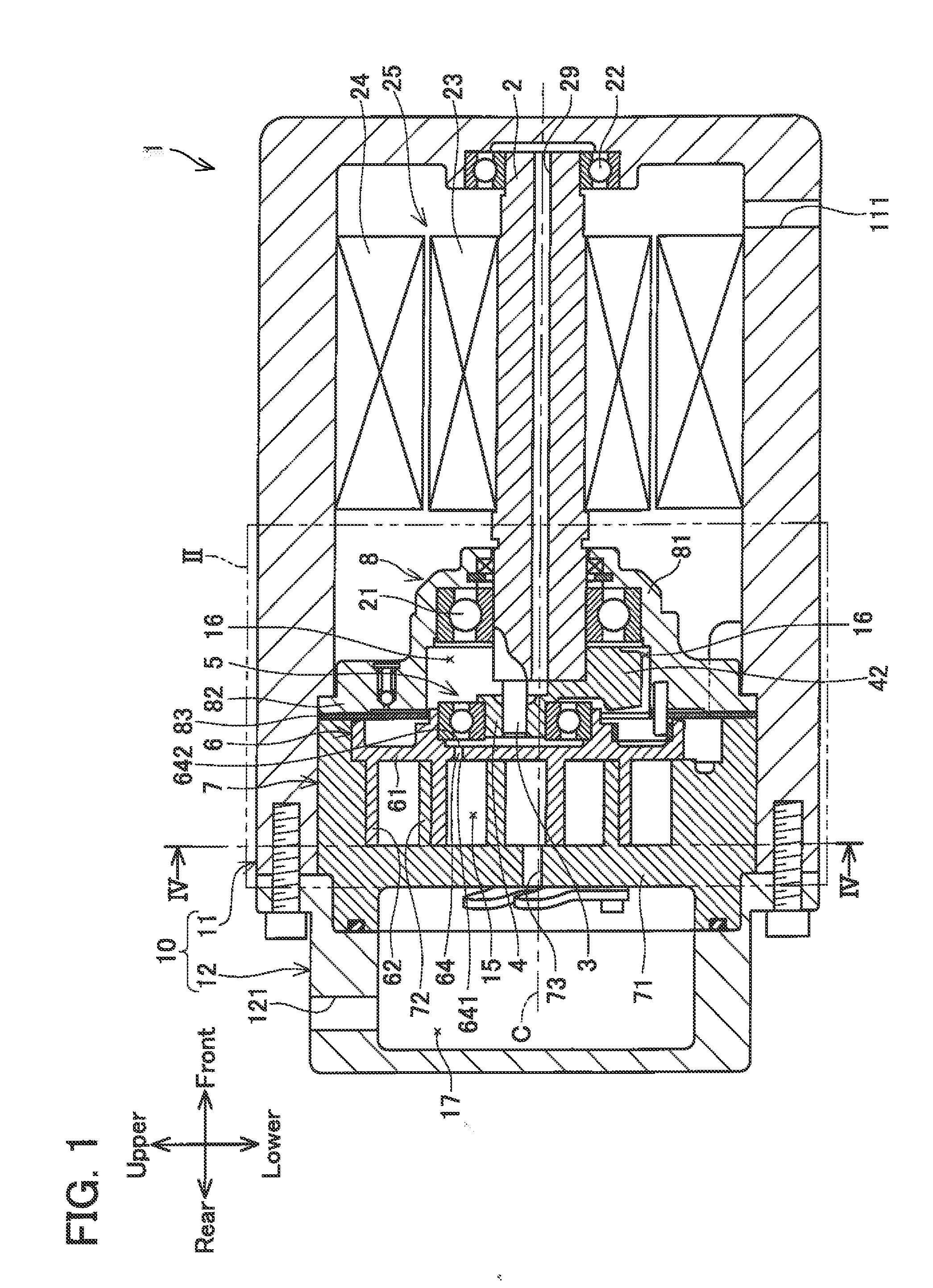
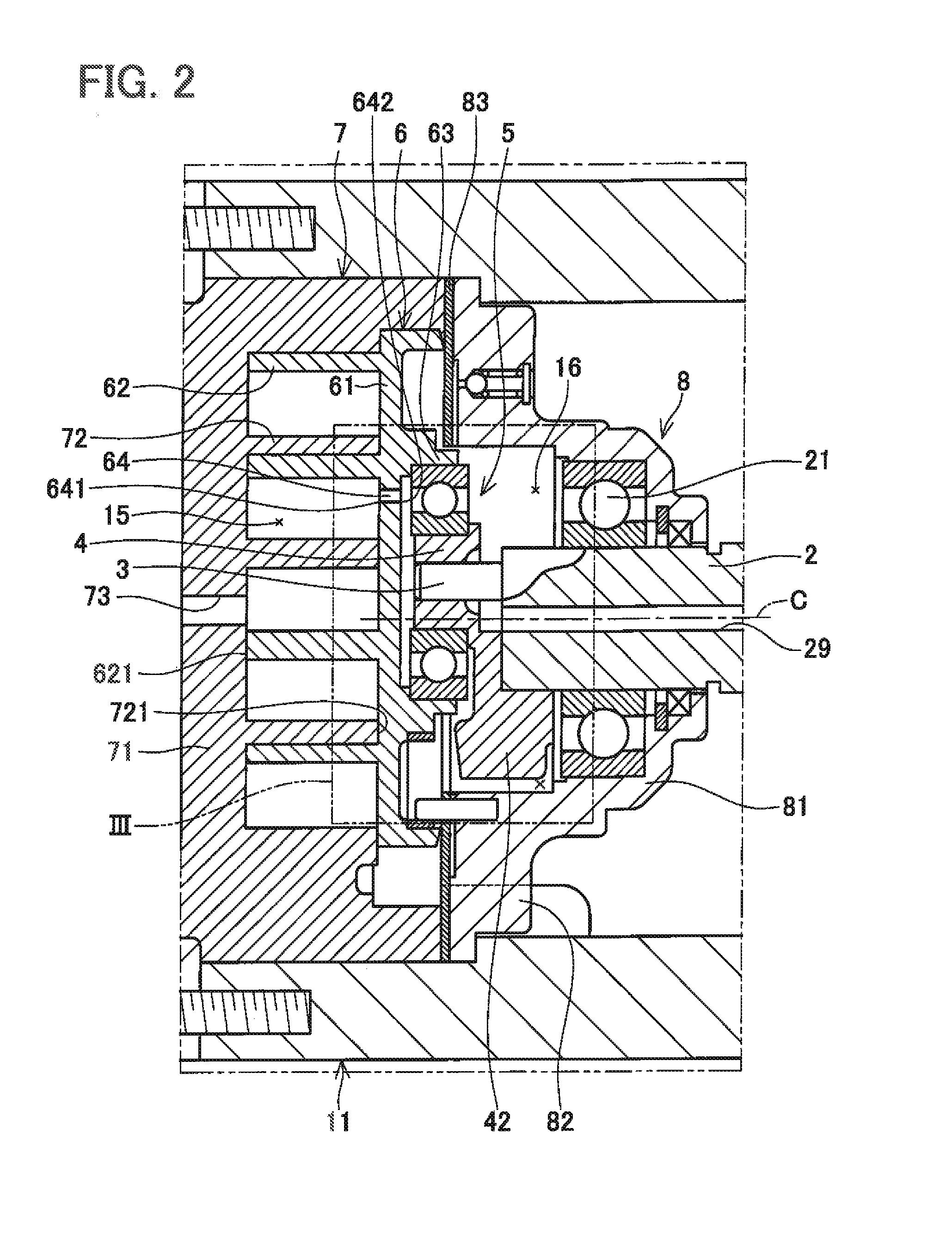
[0007]According to such a configuration, when the rotation shaft is rotated, the orbiting scroll orbits and the refrigerant gas in the compression chamber is compressed. A part of the compressed refrigerant gas is fed toward the back pressure chamber through the gas passage formed in the orbiting base plate of the orbiting scroll. Thereafter, the refrigerant gas passes through gaps between the bush and the bearing in the back pressure chamber. The flow of the refrigerant gas into the back pressure chamber increases the pressure in the back pressure chamber, and this pressure presses the orbiting scroll toward to the fixed scroll. The orbiting scroll is pressed toward the fixed scroll and thus supported, thereby preventing the orbiting scroll to be separated from the fixed scroll when the refrigerant gas is compressed. In this scroll-type compressor, the orbiting base plate of the orbiting scroll comprises the gas passage. Thus, even when the tip-end of the orbiting wall of the orbiting scroll is not separated from the fixed scroll, the refrigerant gas can flow from the compression chamber toward the back pressure chamber. As a result, it is possible to suppress repeated contact and separation between the orbiting scroll and the fixed scroll and suppress the collision of the orbiting scroll on the fixed scroll. Therefore, it is possible to operate the scroll-type compressor silently. Moreover, an area facing an opening portion of the gas passage has high pressure close to discharge pressure because the refrigerant gas taken in on the outer circumference of the compressor is compressed as it moves toward a center side. Thus, it is possible to certainly increase pressure of the back pressure chamber and promote lubrication of the bearing and the bush by lubricating oil contained in the refrigerant gas.

Problems solved by technology

Such movement of the orbiting scroll causes repeated contact and separation between the orbiting scroll and the fixed scroll, and noises and vibration may be occurred when the orbiting scroll is brought into contract with the fixed scroll.

Method used


Image

  • Scroll-type compressor
  • Scroll-type compressor
  • Scroll-type compressor

Examples


Embodiment Construction

[0016]Representative, non-limiting examples of the present invention will now be described in further detail with reference to the attached drawings. This detailed description is merely intended to teach a person of skill in the art further details for practicing preferred aspects of the present teachings and is not intended to limit the scope of the invention. Furthermore, each of the additional features and teachings disclosed below may be utilized separately or in conjunction with other features and teachings to provide improved scroll type compressors, as well as methods for using and manufacturing the same.

[0017]Moreover, combinations of features and steps disclosed in the following detailed description may not be necessary to practice the invention in the broadest sense, and are instead taught merely to particularly describe representative examples of the invention. Furthermore, various features of the above-described and below-described representative examples, as well as the...


PUM


Abstract

The orbiting base plate 61 has a compression side surface and a back pressure chamber side surface. The gas passage 64 has an opening 641 in the compression side surface of the orbiting base plate 61 between portions of the orbiting spiral wall 62 that face each other, and the gas passage 64 has an opening 642 in the back pressure side surface at a position that faces an area on a radially inner side than the outer circumference of the bearing 5, so as to feed the refrigerant gas in the compression chamber 15 to the back pressure chamber 16.

Description

TECHNICAL FIELD[0001]The technique disclosed in the present specification relates to a scroll-type compressor comprising an orbiting scroll and a fixed scroll.DESCRIPTION OF RELATED ART[0002]Japanese Patent Application Publication No. 2011-64189 discloses a conventional scroll-type compressor. The conventional scroll-type compressor is provided with an orbiting scroll, a fixed scroll disposed to oppose the orbiting scroll, and a shaft supporting member disposed to oppose the orbiting scroll on the opposite side of the fixed scroll. A compression chamber is foamed between the orbiting scroll and the fixed scroll, and a back pressure chamber is formed between the orbiting scroll and the shaft supporting member. The scroll-type compressor is further provided with a rotation shaft and an eccentric shaft being offset from a rotation center of the rotation shaft. The orbiting scroll is fixed onto the eccentric shaft through a bush and a bearing. The orbiting scroll is provided with an orb...

Claims


Application Information

Patent Timeline
Patent Type & Authority Applications(United States)
IPC IPC(8): F04C29/00F01C21/02F04C18/02
CPCF04C29/0035F04C18/0215F01C21/02F04C18/0261F04C23/008F04C29/0021F04C29/06F04C27/005
Inventor YAMAZAKI, JUNNISHIZAWA, ATSUSHIMAEMURA, KENJIMURASE, MUNEHARU
Owner TOYOTA IND CORP
Why Eureka
Try Eureka