Ball joint and dust cover

Active Publication Date: 2020-09-10
NOK CORP
View PDF4 Cites 0 Cited by
  • Summary
  • Abstract
  • Description
  • Claims
  • Application Information

AI Technical Summary

Benefits of technology

The invention aims to prevent the dust cover from touching the flange portion of the ball stud, which can help to improve the performance of the product.

Problems solved by technology

However, with this technique, there are cases where, in a device mounted with the ball joint, the outer diameter of the body portion cannot be increased for preventing the body portion from contacting other members.
Consequently, there are cases where the amount of deformation of the body portion is limited so that it is not possible to fully respond to a swinging motion of the ball stud.
However, in the case where the bellows-shaped body portion 710 is employed, a problem may arise that the body portion 710 comes in contact with the ball stud 100 when the body portion 710 deforms.

Method used


Image

  • Ball joint and dust cover
  • Ball joint and dust cover
  • Ball joint and dust cover

Examples


embodiment

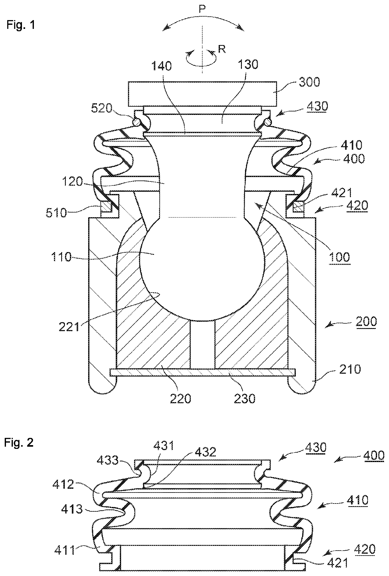
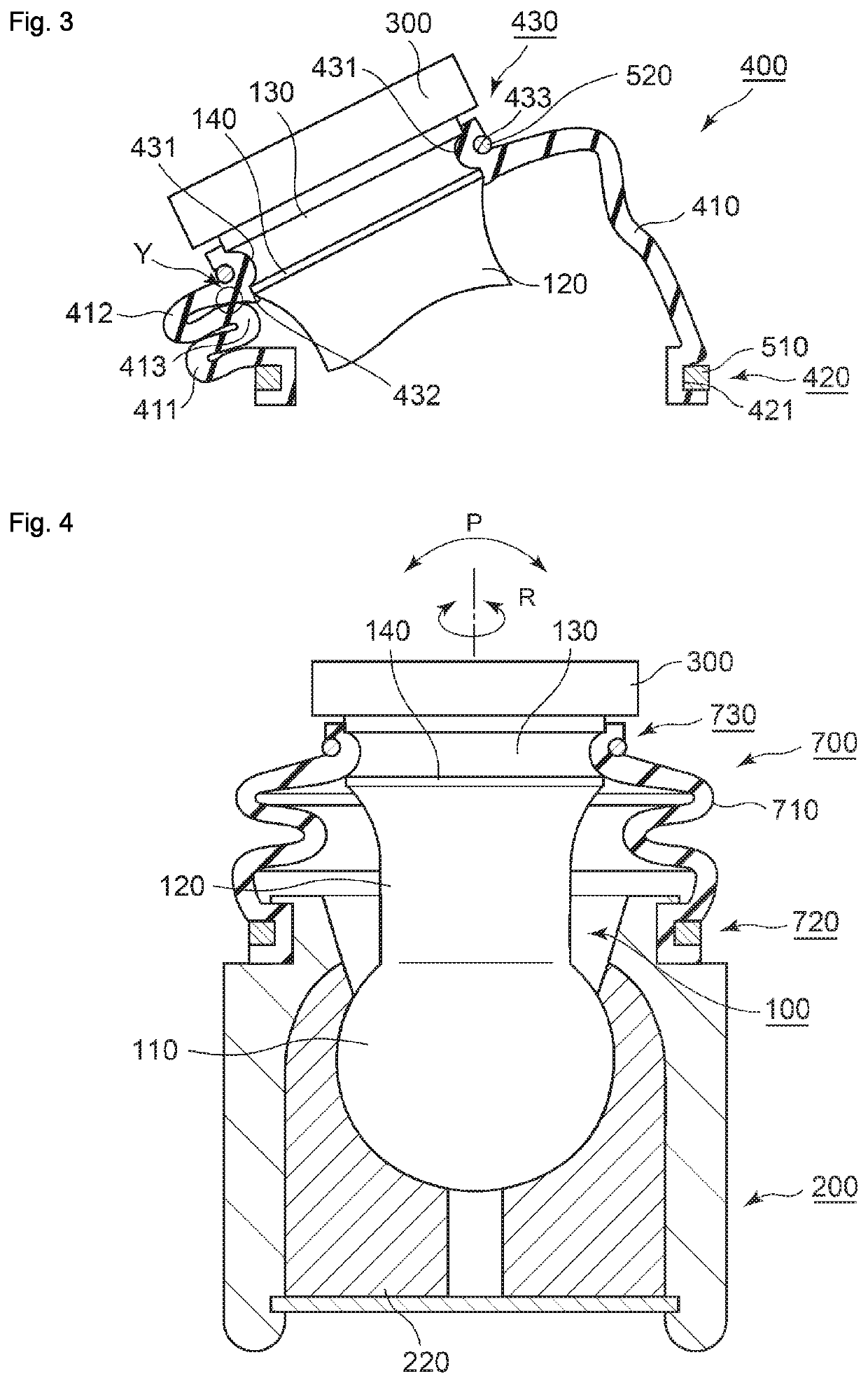
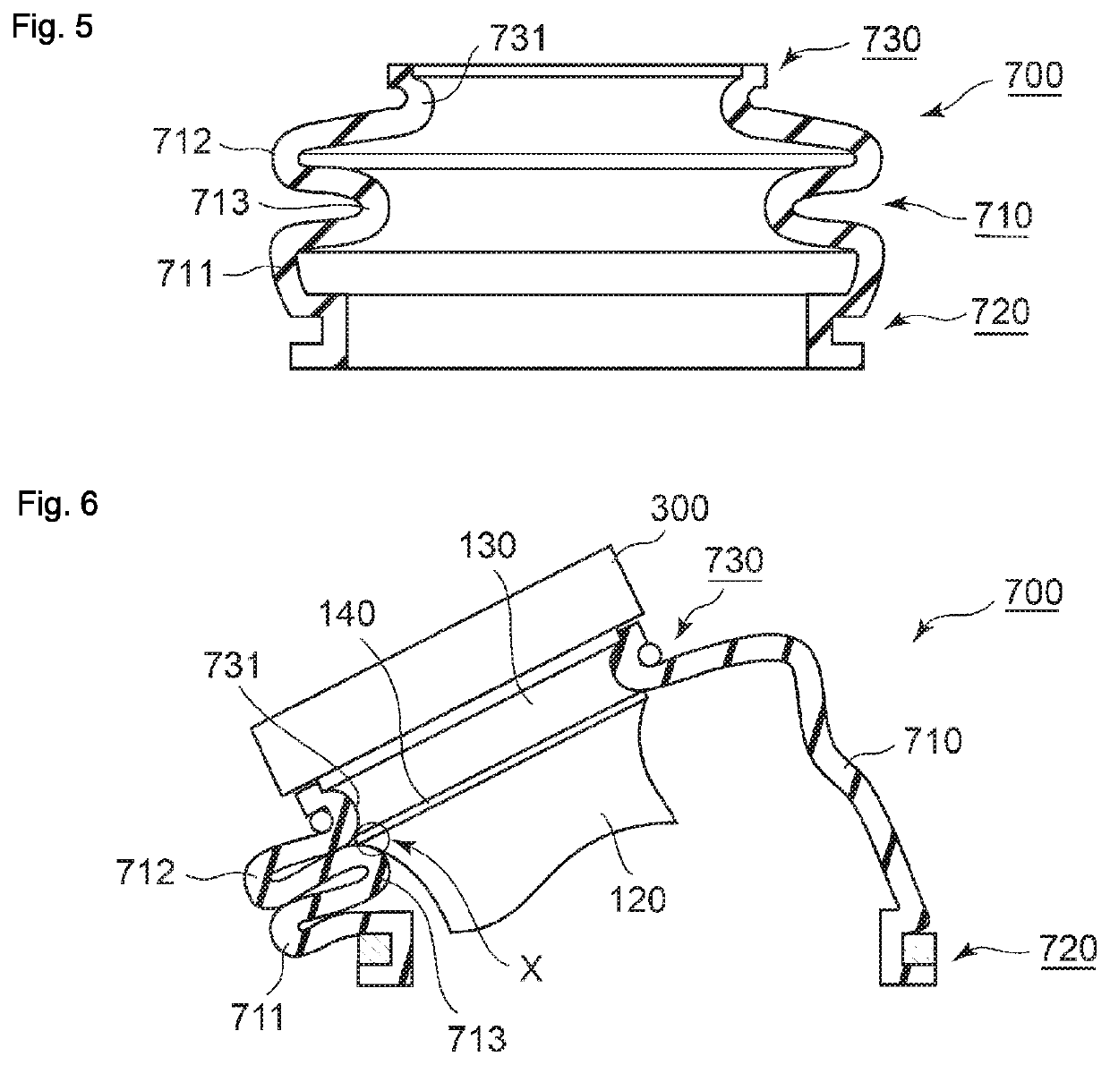
[0039]Referring to FIGS. 1 to 3, a ball joint and a dust cover according to an embodiment of the present invention will be described. FIG. 1 is a schematic sectional view of the ball joint according to the embodiment of the present invention. FIG. 1 illustrates a sectional view obtained by cutting the ball joint in a plane that includes the central axis of a shank portion of a ball stud included in the ball joint. FIG. 2 is a schematic sectional view of the dust cover according to the embodiment of the present invention. FIG. 2 illustrates a sectional view obtained by cutting the dust cover in a plane that includes the central axis of the annular dust cover in a state where the dust cover is not deformed. FIG. 3 is a schematic sectional view illustrating a state of the main part of the ball joint when the ball stud swings, according to the embodiment of the present invention.

[0040]

[0041]Referring particularly to FIG. 1, the ball joint according to this embodiment will be described. ...


PUM


Abstract

Provided are a ball joint and a dust cover that make it possible to suppress contact of a body portion of the dust cover with the vicinity of a flange portion of a ball stud. A dust cover integrally includes: a deformable bellows-shaped body portion made of an elastic body; a fixed portion made of an elastic body and provided on one end side of the body portion; and a sealing portion made of an elastic body and provided on the other end side of the body portion. The sealing portion includes: an inner peripheral sealing portion configured to be slidable on a part of a shank portion on the opposite side of the shank portion from a spherical portion with respect to a flange portion; and a cover portion that continuously covers, in an outer wall surface of the flange portion, a radially outward tip end portion and a part of a portion that decreases in diameter from the tip end portion toward the spherical portion side.

Description

TECHNICAL FIELD[0001]The present invention relates to a ball joint and a dust cover that are mounted in various devices such as a vehicle.BACKGROUND ART[0002]Conventionally, in a ball joint that is mounted in various devices such as a vehicle, a dust cover is provided to prevent water, dust, and so on from entering a joint portion and to prevent grease from flowing out of the joint portion. Referring to FIGS. 4 to 6, a ball joint and a dust cover according to a conventional example will be described. FIG. 4 is a schematic sectional view of the ball joint according to the conventional example. FIG. 5 is a schematic sectional view of the dust cover according to the conventional example. FIG. 6 is a schematic sectional view illustrating a state of the main part of the ball joint when a ball stud swings, according to the conventional example.[0003]The ball joint according to the conventional example includes a ball stud 100 including a spherical portion 110 at one end of a shank portion...

Claims


Application Information

Patent Timeline
IPC IPC(8): F16C11/06F16J15/52F16J3/04
CPCF16C11/06F16J3/04F16J15/52F16J3/042F16C11/0671F16J3/043
Inventor HIROTA, TAKUMA
Owner NOK CORP
Why Eureka
Try Eureka