
Method and apparatus for transferring electrical power by means of capacitive coupling

a technology of capacitive coupling and electrical power, applied in the direction of electric variable regulation, process and machine control, instruments, etc., to achieve the effect of reducing the problem of leakag

Active Publication Date: 2015-04-09
EGGTRONIC ENG SPA
View PDF9 Cites 20 Cited by
  • Summary
  • Abstract
  • Description
  • Claims
  • Application Information

AI Technical Summary

Benefits of technology

The invention aims to provide a method and device for transferring electricity to a charging device that effectively reduces the issue of leakage, which is common in current DC / DC converters.

Problems solved by technology

Increasing the frequency of the tension waves leads tendentially to the drawback of increasing the leakages in the ferromagnetic material which realises the magnetic circuit of the transformer and the dynamic leakage in the active switch during the switching on and off of the active switch, which sets a limit to the maximum frequency of the tension waves which can be generated by the HF source and thus to minimum dimension of the transformer and the heat removing elements of the heat dissipated in the converter.

Method used


Image

  • Method and apparatus for transferring electrical power by means of capacitive coupling
  • Method and apparatus for transferring electrical power by means of capacitive coupling
  • Method and apparatus for transferring electrical power by means of capacitive coupling

Examples


Embodiment Construction

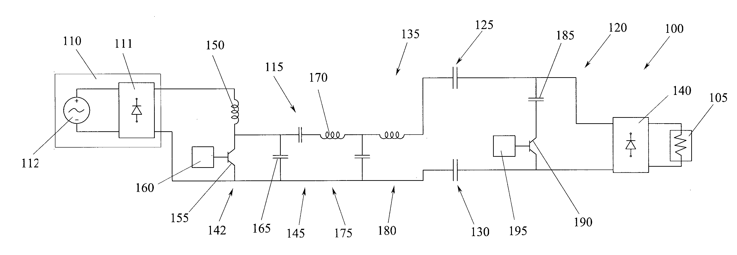
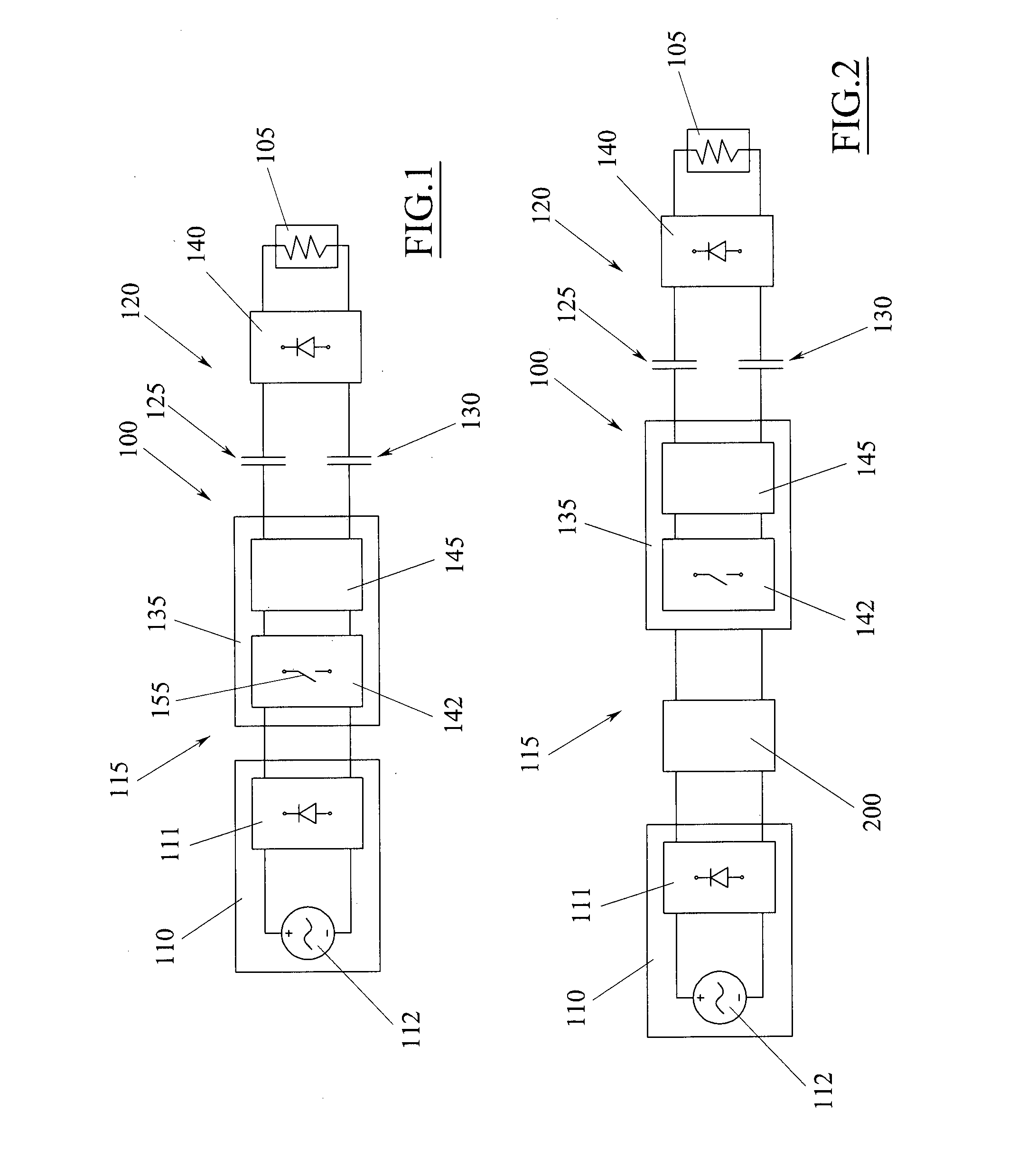
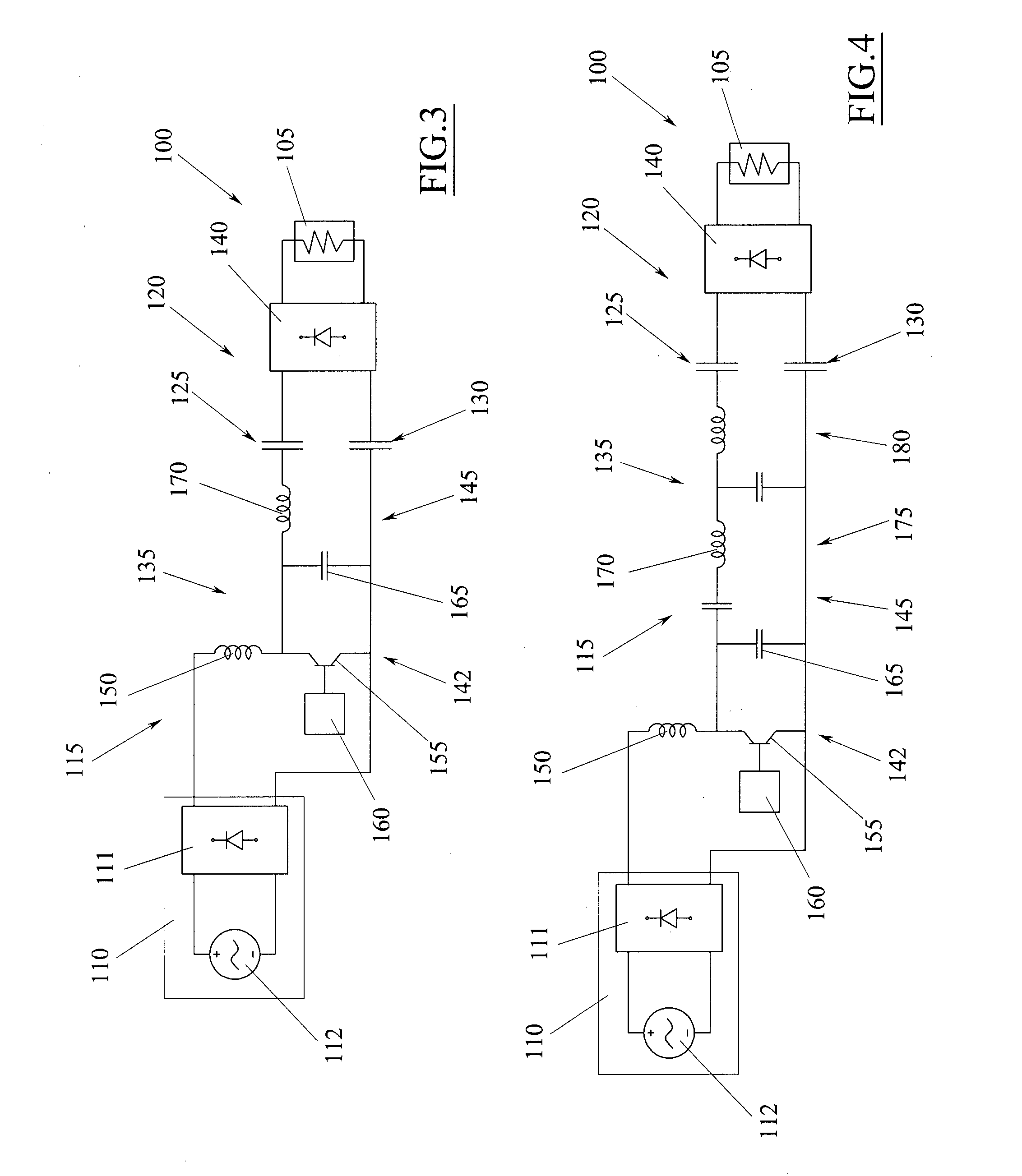
[0117]As shown in FIG. 1, an embodiment of the present invention provides an apparatus 100 for transferring electrical power to an electrical charging device 105.

[0118]The electrical charging device 105 may be for example any electric or electronic device that must be powered to enable operation and / or to charge the internal batteries of the device itself. Classic examples of this type of electrical / electronic device are mobile phones, computers, televisions and others besides.

[0119]From a circuit point of view, the apparatus 100 shown in the example of FIG. 1 is a DC / DC converter, which is suitable for transferring electric power from a DC tension source 110 to a charging device 105, which is here generally denoted by an electrical resistance symbol.

[0120]The DC tension source 110 may be for example a battery.

[0121]Alternatively, the source 110 could include a rectifier 111, for example, a diode bridge, a single diode, a coupled double diode, or another synchronous rectifier, which...


PUM


Abstract

A method and an apparatus for transferring electric power to an electrical load (105); the method comprising steps of: converting a direct electric current into an electric tension wave, applying the electric tension wave in inlet to at least a couple of electric capacitors (125, 130); supplying the electrical load (105) with the electric tension in outlet from the capacitors (125, 130).

Description

TECHNICAL FIELD[0001]The present invention relates in general to a method and an apparatus for transferring electrical power to an electrical load. The electrical load can be for example any electrical or electronic device which has to be electrically powered in order for it to function and / or to charge the internal batteries of the device. Classic examples of this type of electric / electronic device are cellular telephones, computers, televisions and the like.PRIOR ART[0002]A solution that is at present very widely used for transferring electric power to a charging device is that of using an AC / DC converter able to convert an alternating current (AC), generated for example by a common electric grid, into a direct current (DC) suitable for supplying the charging device.[0003]To realise an AC / DC converter capable of transferring high electric power to the charging device, with high performance, low encumbrance and low costs, a circuit is generally used having some typical characterist...

Claims


Application Information

Patent Timeline
IPC IPC(8): H02M1/08H02M3/335H02M1/00
CPCH02M1/08H02M2001/0048H02M3/33507H02M3/005H02J50/05H02J50/80H02J7/00034Y02B70/10H02M1/0035H02M1/0058H02M3/338H02J50/12H02J50/70H02M3/3385H02J7/00H02M1/0048
Inventor SPINELLA, IGOR
Owner EGGTRONIC ENG SPA
Learn More