Rotor for rotary electric machine
a rotary electric machine and rotor technology, applied in the direction of dynamo-electric machines, magnetic circuit rotating parts, magnetic circuit shape/form/construction, etc., can solve the problems of reducing marketability, vibration and/or sound,
- Summary
- Abstract
- Description
- Claims
- Application Information
AI Technical Summary
Benefits of technology
Problems solved by technology
Method used
Image

Examples
first embodiment
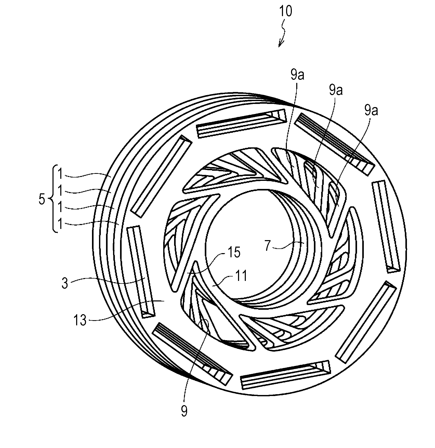
[0040]As illustrated in FIGS. 3 and 4, a rotor 10 for a rotary electric machine according to the present embodiment is formed of a plurality of stacked steel plates 1, and includes a rotor core 5 having a plurality of (8) magnet insertion holes 3 which are formed at every first circumferential space (45° space), permanent magnets (not illustrated) each of which is inserted in a corresponding magnet insertion hole 3, and a rotor shaft (not illustrated) inserted in a shaft hole 7 which is formed at the center of the rotor core 5.
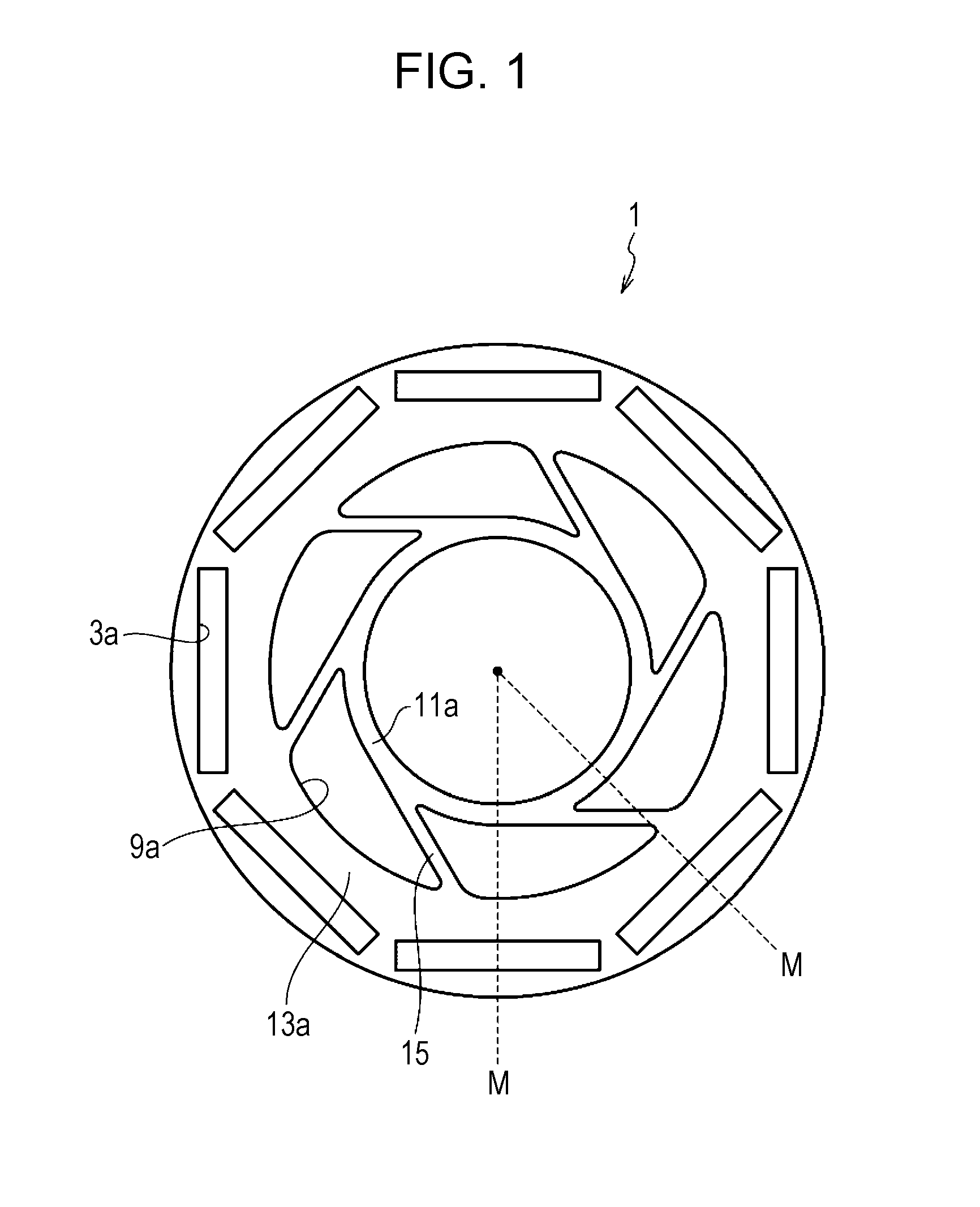
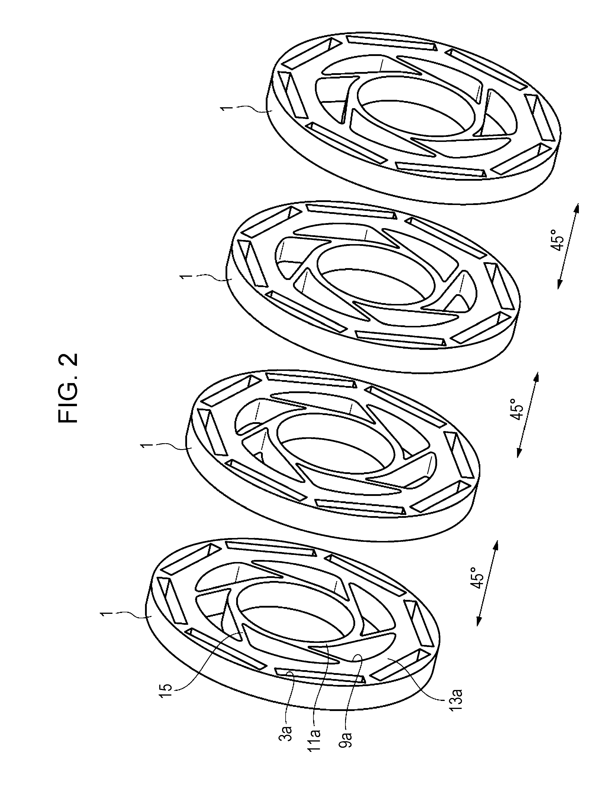
[0041]As illustrated in FIG. 1, each of the steel plates 1 included in the rotor core 5 has a plurality of (8) magnet insertion piece holes 3a which are formed at every first circumferential space (45° space) circumferentially, and a plurality of (6) through piece holes 9a which axially penetrate the steel plate 1 at every second circumferential space (60° space) on the radially inner side of the magnet insertion piece holes 3a.
[0042]In the steel plate 1, a r...
second embodiment
[0059]Next, a rotor for a rotary electric machine according to a second embodiment of the present disclosure will be described. Because the rotor 10 in the present embodiment illustrated in FIGS. 6 and 7 has substantially the same configuration as that of the first embodiment, the same components are denoted by the same symbols and a description thereof will be omitted.
[0060]As illustrated in FIG. 5, in the present embodiment, the through piece holes 9a and the magnet insertion piece holes 3a are formed such that the second circumferential space (60° space) is an integral multiple of the first circumferential space (30° space).
[0061]As illustrated in FIGS. 6 and 7, the rotor core 5 is formed by stacking (for example, rotational stacking) a plurality of steel plates 1 having the same shape such that each one steel plate 1 on top of another steel plate 1 is rotated for the first circumferential space (30°) with respect to the another steel plate 1. Because the second circumferential s...
third embodiment
[0064]Next, a rotor for a rotary electric machine according to a third embodiment of the present disclosure will be described. Because the rotor 10 in the present embodiment illustrated in FIGS. 10 and 11 has substantially the same configuration as that of the first and second embodiments, the same components are denoted by the same symbols and a description thereof will be omitted.
[0065]As illustrated in FIG. 8A, the steel plate 1 in the present embodiment is the same as the steel plate 1 (FIG. 1) in the first embodiment, and hereinafter may be referred to as a first steel plate 1A for the sake of description. The steel plate 1 illustrated in FIG. 8B is obtained by turning (flipping) over the first steel plate 1A, and hereinafter may be referred to as a second steel plate 1B for the sake of description.
[0066]FIG. 9 illustrates a first core 17 in which a plurality of first steel plates 1A is stacked in a predetermined direction, and a second core 19 in which a plurality of second st...
PUM
 Abstract
Description
Claims
Application Information
 - R&D
- Intellectual Property
- Life Sciences
- Materials
- Tech Scout
- Unparalleled Data Quality
- Higher Quality Content
- 60% Fewer Hallucinations
Browse by: Latest US Patents, China's latest patents, Technical Efficacy Thesaurus, Application Domain, Technology Topic, Popular Technical Reports.
© 2025 PatSnap. All rights reserved.Legal|Privacy policy|Modern Slavery Act Transparency Statement|Sitemap|About US| Contact US: help@patsnap.com