
Cutting shaft for vertical stump grinder

Inactive Publication Date: 2015-03-26
NEW RIVER EQUIP
View PDF10 Cites 7 Cited by
  • Summary
  • Abstract
  • Description
  • Claims
  • Application Information

AI Technical Summary

Benefits of technology

The present invention provides an improved cutting shaft for a vertical stump grinder that allows for replaced cutting teeth or grinding tips without replacing the entire grinding shaft. This decreases downtime and maintenance costs. The technical effect is improved efficiency and cost-effectiveness when removing tree stumps and other debris.

Problems solved by technology

For example, a person could trip over the tree stump and / or potentially injure themselves.
Further, upon performing general maintenance upon the property, including cutting the grass on the property, equipment may contact the elevated stump causing damage to the equipment or potential injury to people in the vicinity.
Additionally, a tree stump may invite unwanted pests that could do damage to the surrounding land and / or surrounding structures.
As a result, stump grinders were developed to remove tree stumps before the stumps could become a safety hazard to the property owner and / or others.
In this manner, the drive shaft and the bearings are below the ground level where each component is exposed to dirt and rocks, which may create undesirable wear and / or damage to the components.
Additionally, debris from grinding the tree stump and surrounding area may include wood and rocks which may be thrown vertically from the grinding area by a horizontal stump grinder, constituting a safety hazard.
Another problem with a horizontal stump grinder is that a wheel with a large diameter is required to grind deep enough to remove the tree stump.
The larger diameter wheel requires more power, which further requires more powerful machinery.
Further, such a large diameter wheel may have a greater tendency to climb up on the stump being removed during operation, which may disturb the vehicle on which the wheel is mounted.
As a result of the issues associated with horizontal stump grinders, prior art vertical stump grinders were developed.
A disadvantage of prior art vertical stump grinders is that, upon continued utilization of the grinder, the teeth attached to the vertical stump grinder shaft may become worn out or broken, and / or otherwise require replacement.
Further, prior art vertical grinders are limited to replacing the entire grinding shaft, or cutting shaft, when the teeth are worn out and / or broken.
In this manner, the entire grinder shaft must be replaced, thus requiring purchasing a potentially costly replacement grinder shaft.
Additionally, the installation cost and corresponding amount of time to install the replacement increases the downtime of the prior art vertical stump grinder.

Method used


Image

  • Cutting shaft for vertical stump grinder
  • Cutting shaft for vertical stump grinder
  • Cutting shaft for vertical stump grinder

Examples


first embodiment

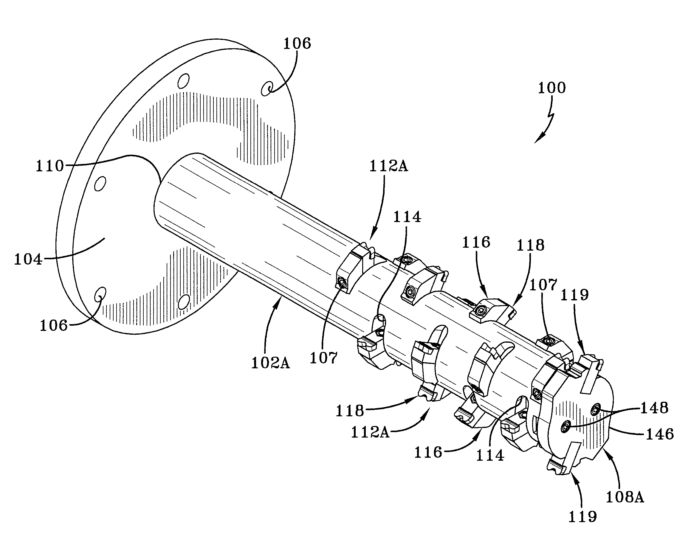
[0047]Base portion 104 is generally disk shaped and is formed with a plurality of openings 106. Fasteners 17 (FIG. 1) are disposed through openings 106 to attached base portion to a vehicle drive source 26 (FIG. 1) of driven equipment, such as skid steer loader 20 (FIG. 1). In this manner, the vehicle provides the power to rotate first embodiment cutting shaft for vertical stump grinder 100, as will be discussed below.

[0048]Base portion 104 is generally rigidly attached to grinding shaft 102A at an intersection 110 by welding, taper lock, or other means known by those in the art. Grinding shaft 102A includes a plurality of cutting teeth 112A disposed about the circumference and along the length of the shaft. Grinding shaft 102A also is formed with a plurality of grooves 114, each one of which corresponds to one of cutting teeth 112A. Each cutting tooth 112A includes a backer support 116 and a cutting portion 118. Backer support 116 is generally rigidly attached to groove 114 of grin...

second embodiment

[0090]Backer support 716 is rigidly attached to interlocking segment 702 generally by welding. Backer support 716 includes a curved portion 719 that minimizes contact with the tree stump and corresponding area while second embodiment of improved cutting shaft for vertical stump grinder 700 is rotating.

[0091]Cutting portion 718 is rigidly attached to backer support 716, generally by brazing, and is generally composed of a metal carbide alloy. As second embodiment of improved cutting shaft for vertical stump grinder 700 rotates, cutting portion 718 cuts and / or grinds the tree stump and corresponding area.

[0092]To further cut and / or grind the tree stump and corresponding area, second embodiment of improved cutting shaft for vertical stump grinder 700 includes interlocking segment 702 on a terminal end 703 that includes a protrusion 721. Protrusion 721 facilitates in grinding and cutting the tree stump and corresponding area and prevents the terminal face of interlocking segment 702 fro...


PUM


Abstract

The invention relates to a stump grinder that rotates about a vertical axis and includes an improved cutting shaft. The improved cutting shaft includes a base portion attached to a drive source, and a grinding shaft attached to and extending downwardly from the base portion. The grinding shaft includes replaceable cutting teeth and a replaceable grinding tip.

Description

CROSS-REFERENCE TO RELATED APPLICATION[0001]This application claims the benefit of U.S. Provisional Patent Application Ser. No. 61 / 882,696, filed Sep. 26, 2013.BACKGROUND OF THE INVENTION[0002]1. Field of the Invention[0003]The invention relates generally to the art of removing tree stumps with a grinding shaft. More particularly, the invention relates to a grinding shaft that rotates. More specifically, the invention relates to a stump grinder that rotates about a vertical axis and includes a replaceable cutting portion and a replaceable grinding tip.[0004]2. Background Art[0005]The use of a grinding apparatus having an elongated grinding wheel rotatable about a horizontal axis has been very popular in the stump grinding industry for many years. Generally, the grinding wheel that rotates about a horizontal axis removes tree stumps to allow the property owner to remove tree stumps before the tree stump causes damage to people and / or property. For example, a person could trip over th...

Claims


Application Information

Patent Timeline
IPC IPC(8): A01G23/06B23D61/06
CPCB27B33/20A01G23/067B23D61/003
Inventor PAUMIER, JAMES J.MATTISON, TODD D.MATTISON, DAVID B.
Owner NEW RIVER EQUIP
Learn More