Electric machine with closed circuit air cooling

a closed circuit air cooling and electric machine technology, applied in the direction of cooling/ventilation/heating modification, dynamo-electric machines, supports/encloses/casings, etc., can solve the problems of increasing the size of the electric machine, the electric machine has to be heated out, and the space demand of the cooling air circuit is enlarged, so as to reduce the size and reduce production and maintenance costs.

Inactive Publication Date: 2015-03-19
GE RENEWABLE TECH
View PDF7 Cites 1 Cited by
  • Summary
  • Abstract
  • Description
  • Claims
  • Application Information

AI Technical Summary

Benefits of technology

[0009]It is one objective of the claimed invention to provide an electric machine with a closed circuit air cooling with a reduced size and lower production and maintenance costs.
[0011]By using the housing as a part of a heat exchanger, it is no longer necessary to install a separate heat exchanger inside the housing and forcing the warm cooling air through this heat exchanger. This means that the cooling circuit can be designed with less space demand and since the housing has a rather great surface an efficient heat transfer from inside the housing to an ambient heat sink is achieved.
[0012]A further advantage of this great cooling surface is that a temperature difference between the warm cooling air inside the housing and the ambient heat sink outside the housing may be rather small. This reduces the temperature inside the housing.
[0013]The claimed double function of the housing as a cover for the electric active components and as a heat exchanger allows a more compact design of the electric machines thus leading to reduced space requirements and production costs.
[0016]This means, that at least a part of the housing functions as a heat exchanger and eliminates heat from the cooling air before the cooling air in its closed circuit is again vented through the active components of the electric machines.
[0017]To improve the heat transfer from the cooling air to the ambient heat sink it is preferred, that at the further section of the cooling circuit the housing is at least partially equipped with one or more cooling fins. These cooling fins may be located inside the housing so that they absorb heat from the cooling air or they may alternatively or additionally be located outside the housing to improve the heat transfer from the housing to the ambient.

Problems solved by technology

Even in the best electric machines conversion losses occur resulting in heat that has to be transferred out of the electric machine to avoid overheating and / or damage.
This results in an enlarged space demand of the cooling air circuit and consequently the size of the electric machine increases.
These additional pumps are extra components that are prone to failure.
In other words, the provision of additional pumps may impair the reliability of the apparatus.

Method used


Image

  • Electric machine with closed circuit air cooling
  • Electric machine with closed circuit air cooling
  • Electric machine with closed circuit air cooling

Examples


Embodiment Construction

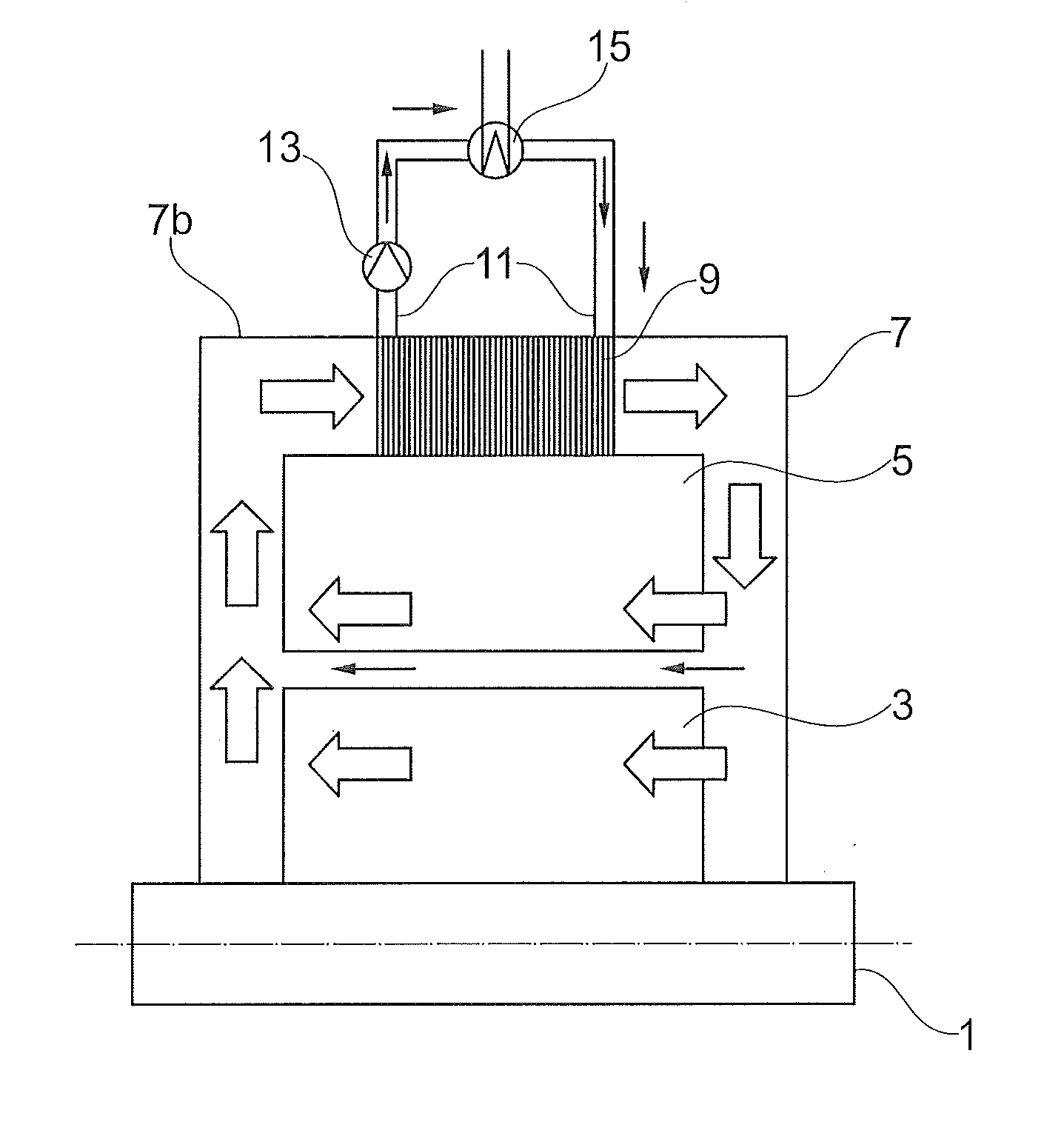
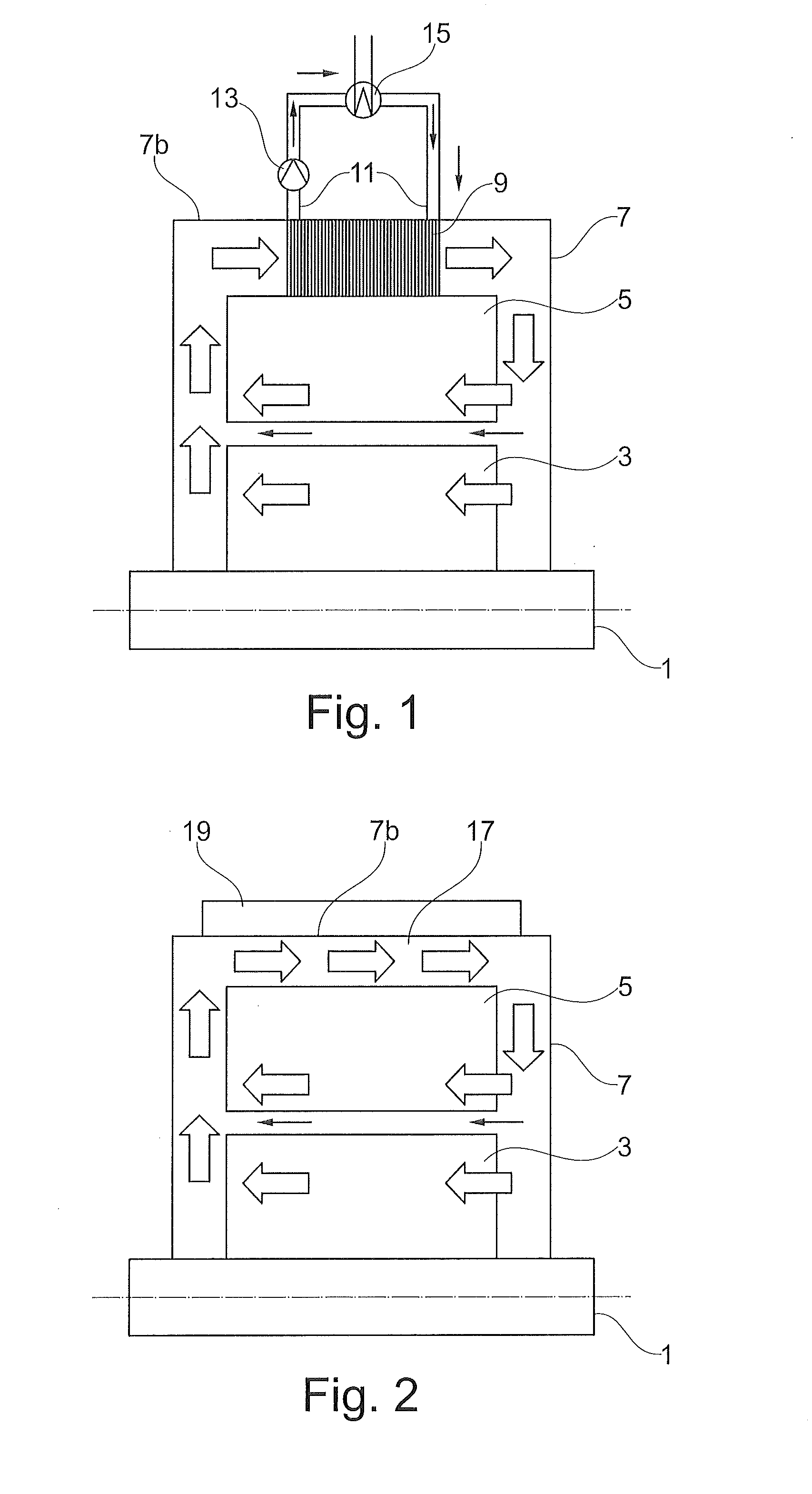
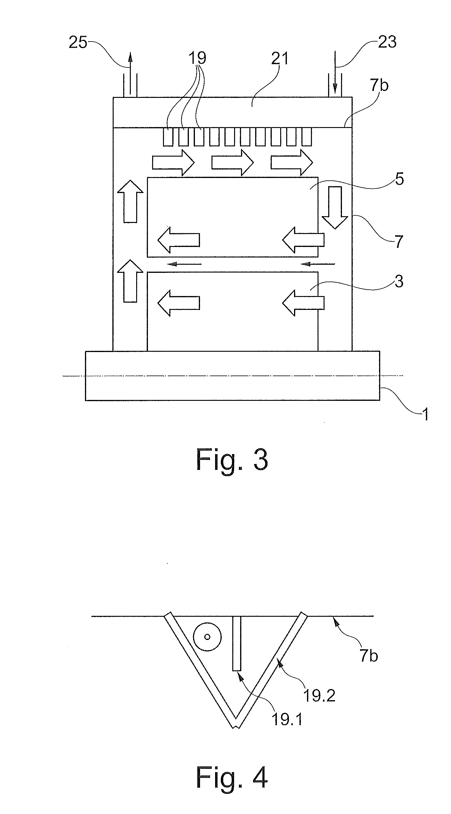
[0028]FIG. 1 shows a schematic illustration of a conventional machine, comprising a shaft 1, a rotor 3, attached to the shaft 1, a stator 5 and a housing 7. The housing 7 makes sure, that neither dirt nor humidity may enter the electric machine and cause trouble.

[0029]Inside the housing 7 a closed circuit of cooling air (illustrated by broad arrows without reference numbers) is active. The ventilation means that drive the cooling air through the rotor 3, a gap between rotor 3 and stator 5 and / or through the stator 5 are not shown in the figures.

[0030]When flowing through the stator 5, the rotor 3 and the gap between stator 5 and rotor 3 the cooling air absorbs heat from the active components 3 and 5 and therefore its temperature rises. The part of the cooling circuit is named the first section, where the cooling air absorbs heat from the active components 3 and 5.

[0031]Radially outwards from the stator 5 a heat exchanger 9 is located in the channel that is limited by the outer diame...


PUM


Abstract

An electric machine with a closed circuit air cooling provides using only passive elements to realize an efficient and compact heat transfer from inside the electric machine to an ambient heat sink.

Description

CROSS-REFERENCE TO RELATED APPLICATIONS[0001]This application claims priority to European application 13184550.5 filed Sep. 16, 2013, the contents of which are hereby incorporated in its entirety.TECHNICAL FIELD[0002]The claimed invention is related to electric machines, more specifically to a closed circuit air cooling system of an electric machine.BACKGROUND[0003]Even in the best electric machines conversion losses occur resulting in heat that has to be transferred out of the electric machine to avoid overheating and / or damage.[0004]The term ‘electric machine’ comprises all types of electric motors that convert electric energy into mechanical energy, electric generators for generating electric energy and / or electric converters that convert electric energy (AC or DC) with a certain voltage and / or frequency into an other form of electric energy (AC or DC) with other voltage and / or other frequency.[0005]All these machines have in common that high currents occur and as a result of the...

Claims


Application Information

Patent Timeline
Patent Type & Authority Applications(United States)
IPC IPC(8): H05K7/20H02K9/10
CPCH05K7/202H02K9/10H05K7/20409H02K9/08H02K5/207H02K5/203H02K5/18
Inventor BAUMEISTER, STEFANBOIVENT, ERWANSADEGHI, MOSTAFA
Owner GE RENEWABLE TECH
Why Eureka
Try Eureka