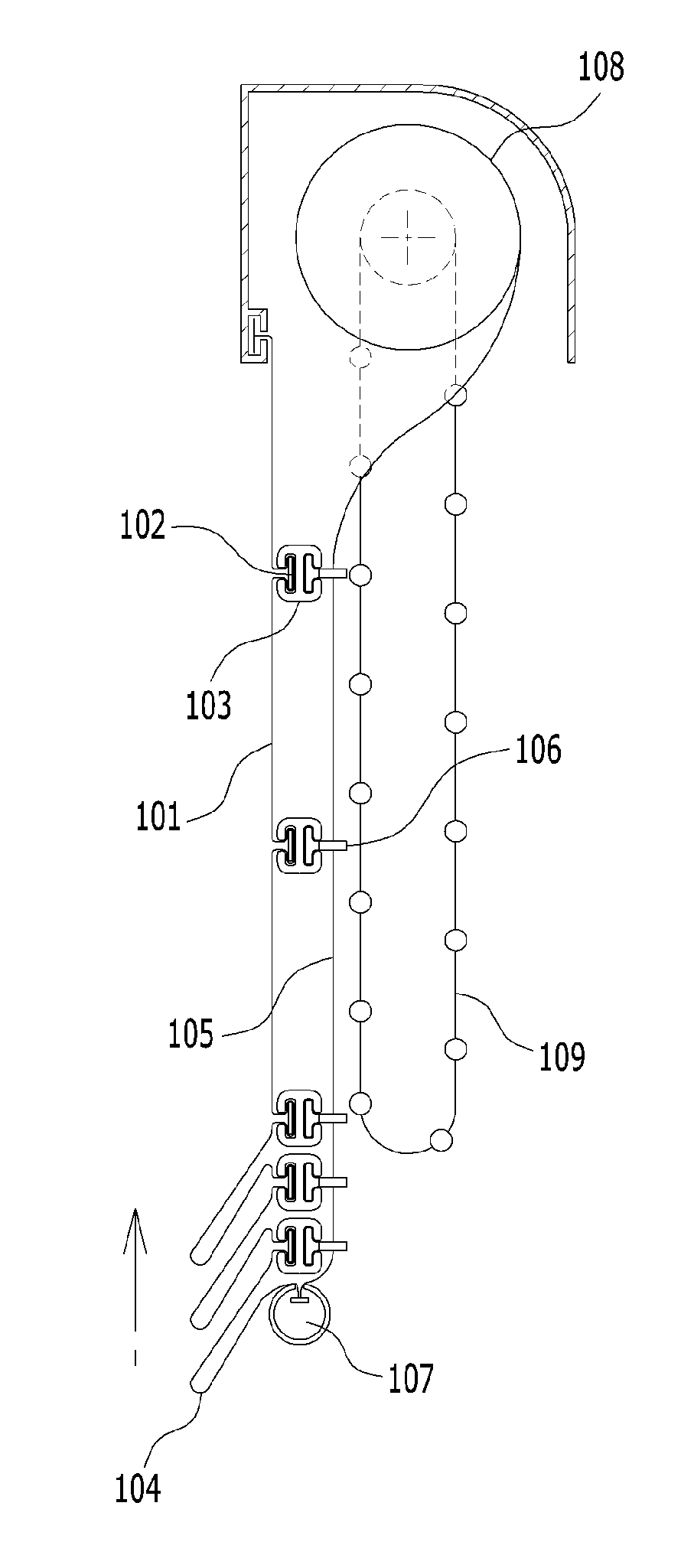
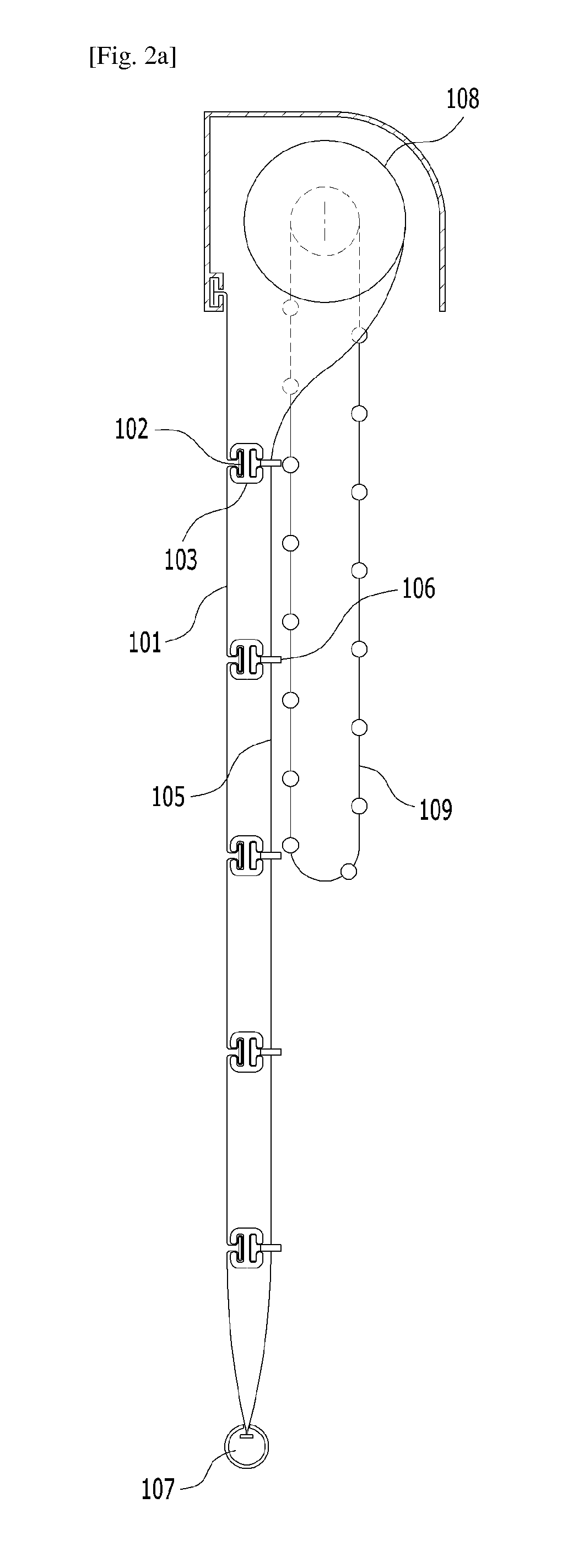
Roman shade type blind cloth
a shade type and blind cloth technology, applied in the direction of shutters/movable grilles, door/window protective devices, wing arrangements, etc., can solve the problems of increasing the manufacturing cost of the blind, decreasing the assembly property for the blind, and increasing the number of components, so as to reduce the production cost, the effect of freely adjusting the length and width of the loop
- Summary
- Abstract
- Description
- Claims
- Application Information
AI Technical Summary
Benefits of technology
Problems solved by technology
Method used
Image
Examples
first embodiment
[0136]FIG. 17a is a detailed view illustrating “A” part of FIG. 15, wherein two rimy sets 215 through which the cord line 214 passes are formed on a back surface of the blind cloth 211 and the cord line 214 is passed through the two ring sets 215 in turn thereby to determine the interval L1 between loops. That is, when the cord line 214 is inserted into each ring set 215 that is formed along a vertical direction of the blind cloth 211, the cord line 214 is passed through only two adjacent ring sets 215 when forming the interval L1 between loops to be narrow as shown in FIG. 17a. On the other hand, the cord line 214 is passed through adjacent three or more ring sets 215 when forming the interval L1 between loops to be wide as shown in FIG. 17b, thereby adjusting easily the interval L1 between loops when assembling the blind.
third embodiment
[0137]FIG. 17c is a detailed view illustrating “A” part of FIG. 15, wherein an interval maintaining member 216 is fitted between the ring sets 215 on a back surface of the blind cloth 211, such that the cord line 214 is passed through one ring set 215, the interval maintaining member 216 and another ring set 215 in turn to determine the interval L1 between loops.
fourth embodiment
[0138]FIG. 17d is a detailed view illustrating “A” part of FIG. 15, wherein a plurality of interval maintaining members 216 are arranged between four ring sets 215, respectively, when forming the interval L1 between loops to be wider such that the cord line 214 is passed through one ring set 215, the interval maintaining members 216 and other ring sets 215 in turn.
[0139]FIGS. 18a and 18b are views illustrating a fifth and sixth embodiments of “A” part of FIG. 15, wherein the interval maintaining member 216 may be formed as a long ring pin-type one side of which is opened such that the ring set 215 is fitted and retracted therethrough, and the size of which is determined such that the interval maintaining member is fitted into two ring sets 215 as shown in FIG. 18a, or it is fitted into simultaneously four ring sets 215 as shown in FIG. 18b, by using a bend-molding or injection-molding method. At this time, the cord line 14 is passed through the interval maintaining member 216 of a r...
PUM
 Abstract
Description
Claims
Application Information
 - R&D
- Intellectual Property
- Life Sciences
- Materials
- Tech Scout
- Unparalleled Data Quality
- Higher Quality Content
- 60% Fewer Hallucinations
Browse by: Latest US Patents, China's latest patents, Technical Efficacy Thesaurus, Application Domain, Technology Topic, Popular Technical Reports.
© 2025 PatSnap. All rights reserved.Legal|Privacy policy|Modern Slavery Act Transparency Statement|Sitemap|About US| Contact US: help@patsnap.com


