
Protective helmet; method for reducing or preventing a head injury

a protective helmet and head technology, applied in helmets, clothing, apparel, etc., can solve the problems of round helmets, excessive head injuries, and inability to meet the needs of consumers,

Inactive Publication Date: 2015-03-19
SHARK
View PDF92 Cites 23 Cited by
  • Summary
  • Abstract
  • Description
  • Claims
  • Application Information

AI Technical Summary

Benefits of technology

The invention relates to a method of testing protective helmets in a pull-off test. The method includes rotating an insert on the shell side with respect to an insert on the head side. This rotation is limited or suppressed by at least one limiting means in the direction of pulling. This limitation or suppression improves the tested helmets' performance in the pull-off test.

Problems solved by technology

Round helmets, seen from the front, appear to be wide and are not successful on the market.
One disadvantage of these protective helmets is that, although they do protect against impacts having a translatory impact with the protective helmet or its shock-absorbing cap, they do not protect against torsional forces which act in an impact, so that excessively severe head injuries occur in many accidents, despite the use of a protective helmet.
It must be evaluated as a disadvantage that the external appearance of the protective helmet is affected negatively by this membrane.
The disadvantage of this approach is that with even a slight movement, the torsional movement can be stuck.
This achieves a good protective effect but this approach is very complex and expensive.
The disadvantage with the prior art mentioned here is that this distance or angle is increased by the sliding of the shells relative to one another with a type of protective helmet that has been described, so that these protective helmets do not perform well in the pull-off tests.

Method used


Image

  • Protective helmet; method for reducing or preventing a head injury
  • Protective helmet; method for reducing or preventing a head injury
  • Protective helmet; method for reducing or preventing a head injury

Examples


Embodiment Construction

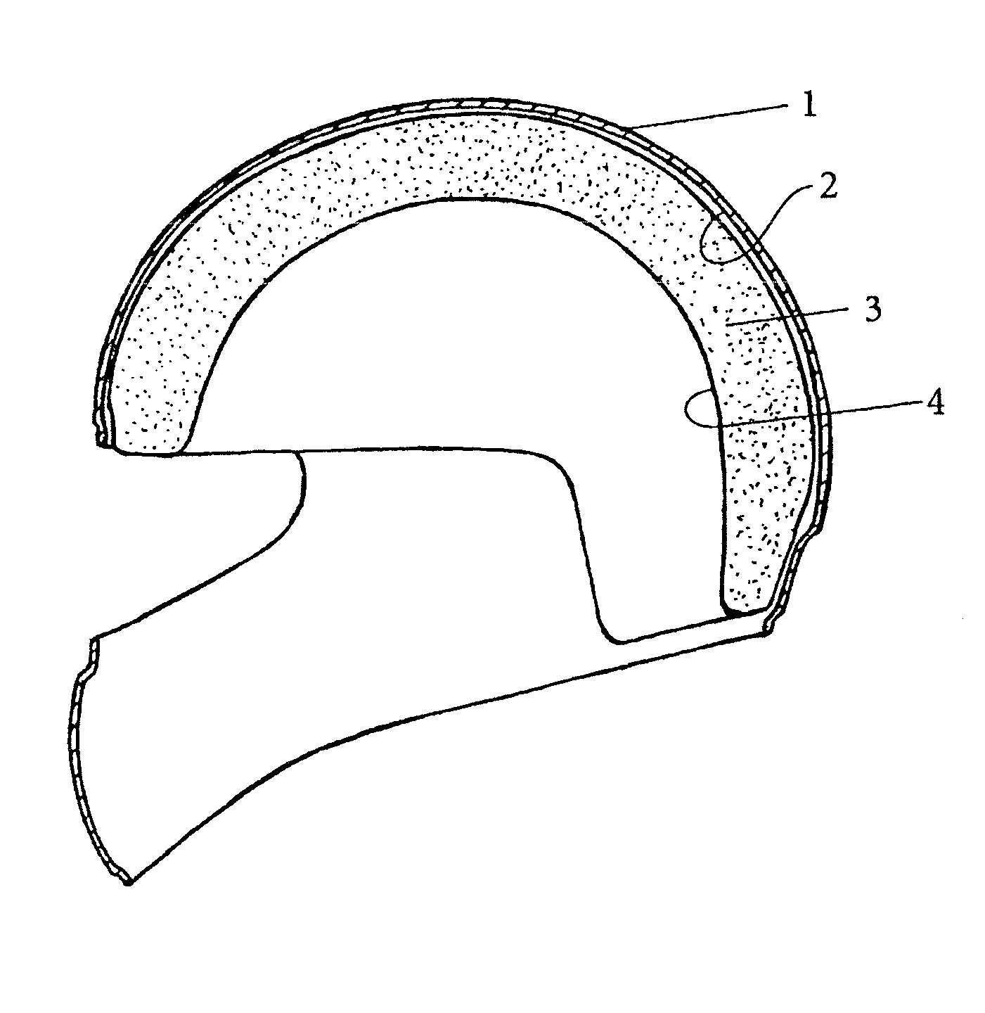
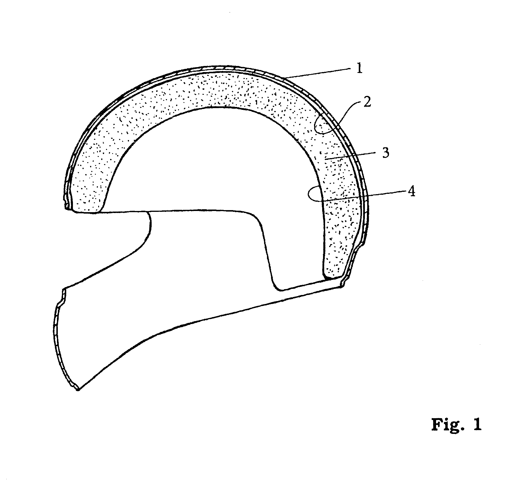
[0034]FIG. 1 and FIG. 2 show sectional diagrams of a traditional protective helmet consisting of a hard exterior shell 1 having the interior head protection system 3 situated on the inside 2. The interior head protection system 3 has an inside 4, whose oval shape is adapted to the shape of a human head 5 (see FIG. 2).

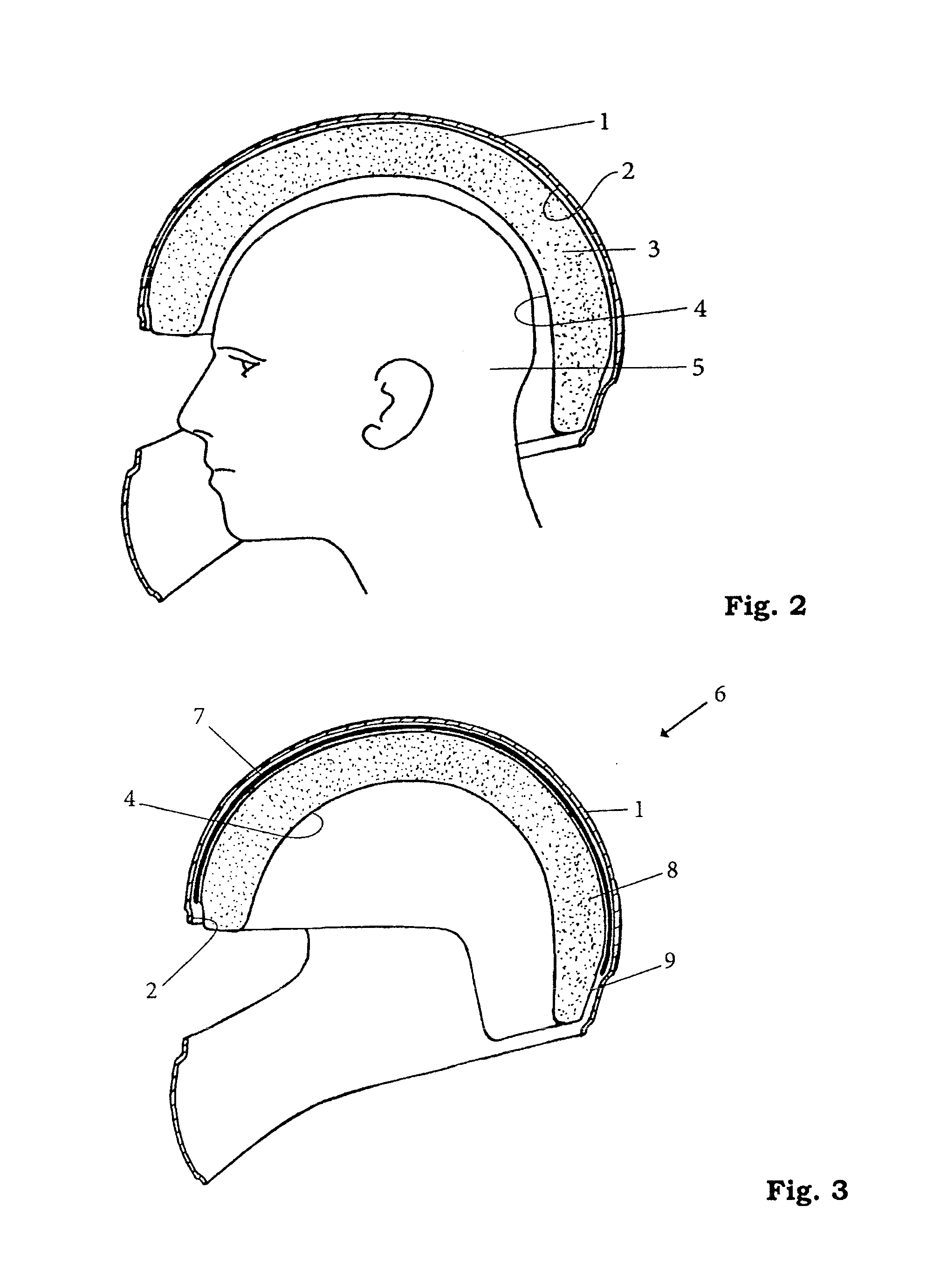
[0035]FIG. 3 and FIG. 4 show sectional diagrams of a first embodiment of the traditional protective helmet 6. The shock-absorbing or shock-absorbing and comfort-imparting interior head protection system surrounded by the hard exterior shell 1 is divided into an insert 7 on the shell side and an insert 8 on the head side, such that the outside 9 of the insert 8 on the head side, facing away from the head 5 (see FIG. 4) has a spherical surface at least in part, and the outside 9 of the insert 8 on the head side corresponds to the inside of the insert 7 on the shell side.

[0036]The insert 7 on the shell side and the insert 8 on the head side of the interior head protection ...


PUM


Abstract

A protective helmet for a head and a method for reducing or preventing a head injury wherein the protective helmet is equipped with an outer shell made of a hard material and an interior head protection system, which is arranged on the inside of the outer shell and absorbs an impact with the head. The interior head protection system is subdivided into an insert on the shell side and an insert on the head side, and the mutually facing sides of the insert on the head side and the insert on the shell side correspond at least partially to one another. The insert on the shell side can be rotated in at least one direction with respect to the insert on the head side, wherein at least one elevation is provided on the insert on the shell side, such that this elevation engages in a recess which is larger than the elevation and is situated on the insert on the head side and / or at least one elevation is provided on the insert on the head side, engaging in a recess which is larger than the elevation on the insert on the shell side.

Description

PRIOR ART[0001]The invention relates to a protective helmet according to the generic type of claim 1 and a method for reducing or preventing a head injury according to the generic type of claim 8.[0002]There are various known protective helmets, which serve to protect the head of the wearer from injury. These protective helmets are adapted to the human head, which has an oval shape, as seen from above, which can be further differentiated into a “round oval” shape and a “long oval” shape. The usual protective helmets on the market assume this shape to resemble the human head, but in particular to look small. The only helmets available on the market are those which look narrow, as seen from the front, and appear to be small. Round helmets, seen from the front, appear to be wide and are not successful on the market.[0003]As a rule, these protective helmets, which may have a variety of designs, depending on the intended application, consist of an external shell made of a hard material, ...

Claims


Application Information

Patent Timeline
Patent Type & Authority Applications(United States)
IPC IPC(8): A42B3/04A42B3/12
CPCA42B3/12A42B3/0406A42B3/064
Inventor SCHIMPF, OLIVER
Owner SHARK
Learn More