Illumination system

a technology of light emission and beam, applied in the field of light emission system, can solve the problems that the light emitted by the led cannot be easily shaped or collimated, and achieve the effect of enhancing the ability to shape the beam in the desired way

Active Publication Date: 2015-03-12
AMS SENSORS SINGAPORE PTE LTD
View PDF7 Cites 0 Cited by
  • Summary
  • Abstract
  • Description
  • Claims
  • Application Information

AI Technical Summary

Benefits of technology

[0007]It is an objective of the present invention to improve an illumination system having at least one light source and at least one micro-optical element comprising at least two sections with different optical microstructures in such a way that the ability to shape the beam in a desired way is enhanced.
[0008]Especially, it would be desirable to have a solution that allows better collimation of the light distribution of light emitted by an LED.
[0009]It would also be desirable to have a solution that allows generation of a rotationally asymmetric, e.g. rectangular, output light distribution.
[0010]It is a further object of the invention to provide a structure having small dimensions such that it can easily be implemented in small electronic devices, such as mobile phones or the like. Here, it is especially desirable to provide a collimating lens that is suited for the flash light of digital cameras, e.g. as comprised in some mobile phones.
[0012]Due to this principle and contrary to conventional, purely refractive optical elements like spherical lenses, such micro-optical elements have the potential to shape the initially emitted light in almost any manner. This is especially beneficial in combination with one or more LED(s) as a light source. A further advantage is that micro-optical elements can be shaped essentially flat and can be manufactured in a mass process, e.g. by imprinting the desired profile on a transparent substrate.
[0023]The rotational symmetry simplifies the design and manufacture of the microstructures. Nevertheless, the claimed invention allows shaping of a light distribution, e.g. as emitted from a LED, according to given demands. According to preferred embodiments of the present invention, an illumination system with enhanced collimation efficiency, achieved by segmentation of the optical element in radial direction from the optical axis, and an illumination system capable of generating a rectangular or elliptic output distribution, achieved by segmentation of the optical element in azimuthal direction around the optical axis, is provided.

Problems solved by technology

A key problem related to using LED sources is the fact that light emitted by a LED can not be easily shaped or collimated.

Method used


Image

  • Illumination system
  • Illumination system
  • Illumination system

Examples


Embodiment Construction

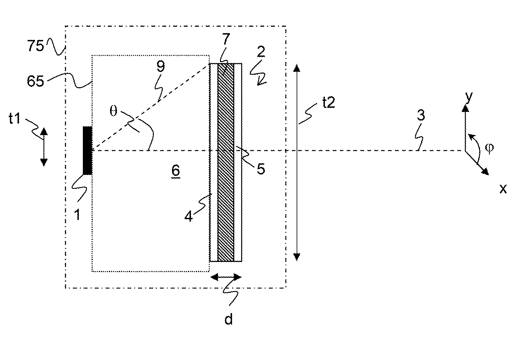
[0055]FIG. 1 shows an illumination system with a light source 1 and an optical element 2 arranged along an optical axis 3. Here and in the following figures, “x” and “y” designate directions perpendicular to one another and to the optical axis 3. The optical element 2 has a first surface 4 acting as an entry face for the light emitted by the light source 1, and on its opposite side a second surface 5 acting as an exit face for the light emitted by the light source 1. At least one of said surfaces 4, 5 is structured by means of optical microstructures 10 (shown in FIGS. 3+4).

[0056]The light source 1, typically a LED, has a transversal dimension t1 that is small compared to the transversal dimension t2 of the optical element 2. Because of the microstructures, the optical element 2 can be manufactured with small dimensions along the optical axis; its thickness d is far smaller than its transversal dimension t2.

[0057]An optical medium 6 between the light source 1 and the optical element...


PUM


Abstract

An illumination system including at least one light source such as an electroluminescent element, e.g. a light emitting diode (LED), and at least one optical element whose surface is structured by diffraction and / or refraction type optical microstructures. In order to shape the beam, the optical element includes at least two sections whose optical microstructures and therefore optical properties are different from one another. The pattern of the microstructures in each of the at least two sections is, at least over a predetermined angular range, rotationally symmetric with respect to the optical axis or another symmetry axis.

Description

BACKGROUND OF THE INVENTION[0001]1. Field of the Invention[0002]The invention relates to an illumination system including at least one light source such as an electroluminescent element, e.g. a light emitting diode (LED), and at least one optical element whose surface is structured by means of diffraction and / or refraction type optical microstructures. The invention further relates to an optical element whose surface is structured by means of diffraction and / or refraction type optical microstructures, and to a collimating lens with such an optical element or such an illumination system.[0003]2. Description of Related Art[0004]LEDs are well known in the art, are available for a large variety of wavelengths, emitting powers and other properties and are used for many appliances. A key problem related to using LED sources is the fact that light emitted by a LED can not be easily shaped or collimated. This is due to the fact that a LED is an extended light source with an active area of t...

Claims


Application Information

Patent Timeline
Patent Type & Authority Applications(United States)
IPC IPC(8): G02B27/30G02B5/18G03B15/05F21V5/00
CPCG02B27/30G03B15/05G02B5/18F21V5/00F21V5/002F21V33/0052G02B5/1885
Inventor DIAS, DANIELKETTUNEN, VILLEROSSI, MARKUS
Owner AMS SENSORS SINGAPORE PTE LTD
Why Eureka
Try Eureka