
Test probe assembly and related methods

a technology of assembly and probe, applied in the field of contact assembly and assembly, can solve the problems of short life span, short life span, and high cost of manufacturing

Active Publication Date: 2015-03-12
XCERRA
View PDF9 Cites 11 Cited by
  • Summary
  • Abstract
  • Description
  • Claims
  • Application Information

AI Technical Summary

Benefits of technology

The present invention relates to a test probe assembly and a method of using it to evaluate electrical performance. The assembly includes a first plunger and a second plunger that are both positioned within a spring. The first plunger has a spring latch at its distal end, while the second plunger has a spring latch at its distal end. The plungers are used to make electrical contact with the inner diameter of the spring. The assembly can be used in a testing apparatus to evaluate electrical performance. Its technical effects include improved accuracy and reliability in evaluating electrical performance, as well as simplified and more efficient assembly and use of the testing apparatus.

Problems solved by technology

A problem associated with these type of external spring probes is the expense to manufacture due to costly machining operations.
A problem with this design is that the components wear out rather quickly and have a short life span requiring constant replacement.

Method used


Image

  • Test probe assembly and related methods
  • Test probe assembly and related methods
  • Test probe assembly and related methods

Examples


Embodiment Construction

[0052]The following detailed description includes references to the accompanying drawings, which form a part of the detailed description. The drawings show, by way of illustration, specific embodiments in which the apparatus may be practiced. These embodiments, which are also referred to herein as “examples” or “options,” are described in enough detail to enable those skilled in the art to practice the present embodiments. The embodiments may be combined, other embodiments may be utilized or structural or logical changes may be made without departing from the scope of the invention. The following detailed description is, therefore, not to be taken in a limiting sense and the scope of the invention is defined by the appended claims and their legal equivalents.

[0053]In this document, the terms “a” or “an” are used to include one or more than one, and the term “or” is used to refer to a nonexclusive “or” unless otherwise indicated. In addition, it is to be understood that the phraseolo...


PUM

PropertyMeasurementUnit
arc angleaaaaaaaaaa
thicknessaaaaaaaaaa
angleaaaaaaaaaa

Abstract

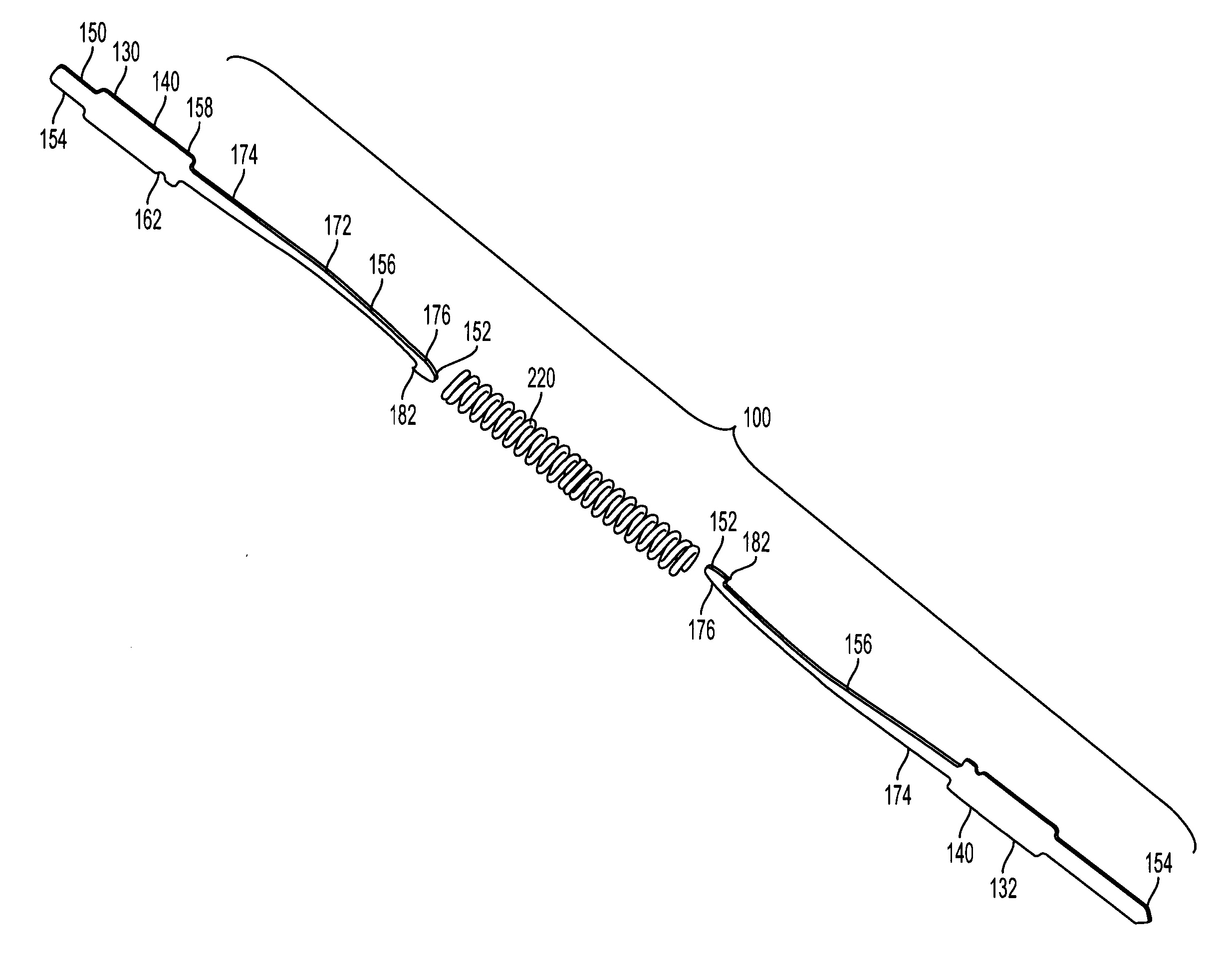
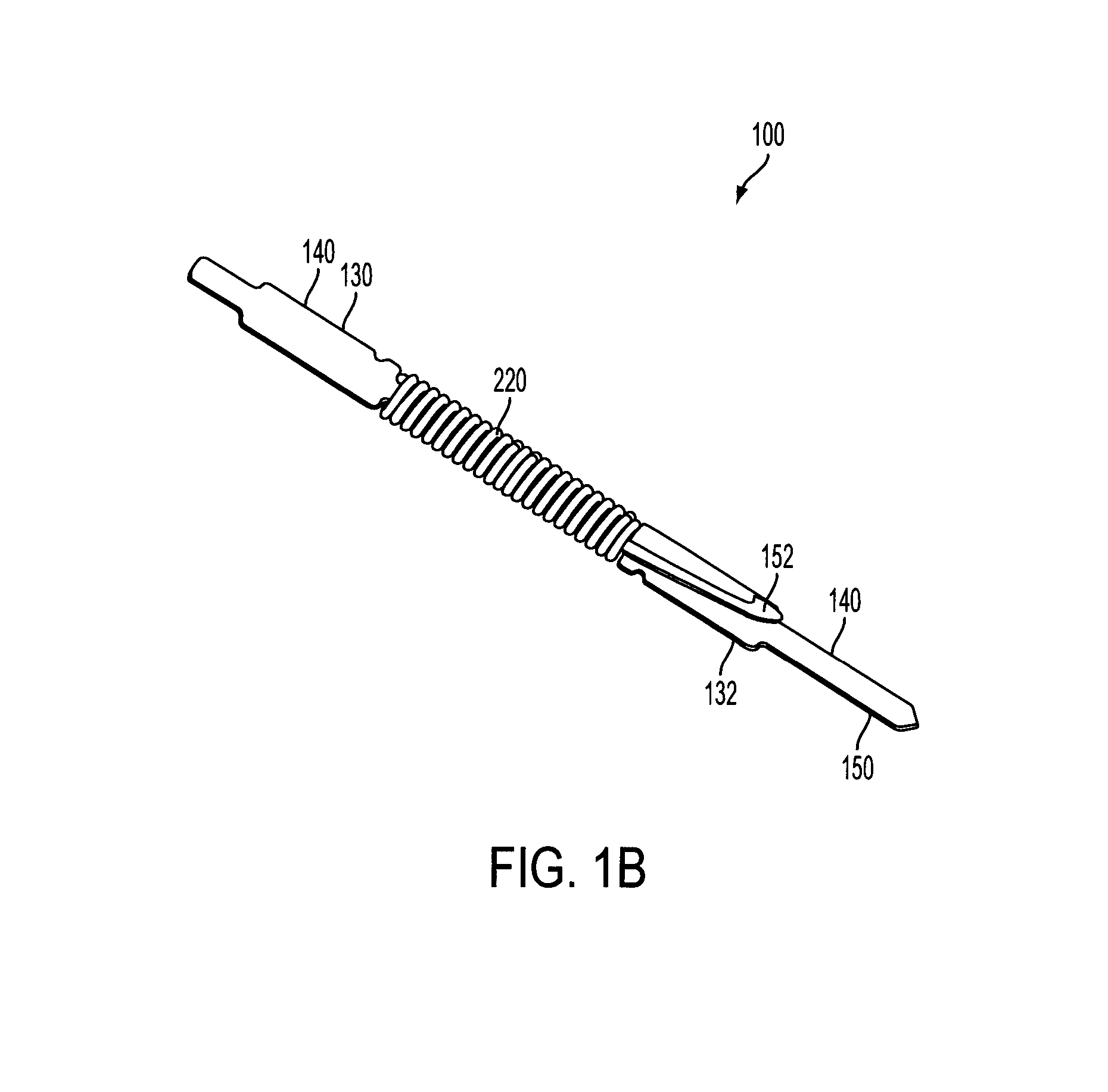
A test probe assembly includes a first elongate electrically conductive plunger that extends from a proximal first plunger end to a distal first plunger end, and is defined in part by a central longitudinal axis. The first plunger has a first spring latch at the distal first plunger end. At least a portion of the first plunger has an arc with a first plunger outer contact point opposite the first spring latch relative to the longitudinal axis. The first plunger is disposed in a spring. The first plunger outer contact point in contact with the inner diameter of the spring, and the first spring latch engages at least a portion of the spring. A method includes disposing a first plunger within a spring along a spring longitudinal axis, disposing a second probe within the spring along the spring longitudinal axis, and engaging the spring latch and the second plunger spring latch with the spring, for instance by capturing an end coil of the spring with the spring latch of at least one of the spring latch or the second plunger spring latch.

Description

RELATED APPLICATION[0001]This applications claims priority under 35 USC 119(e) to provisional application U.S. Ser. No. 61 / 624,083 filed 13 Apr. 2012, which application is incorporated herein by reference.TECHNICAL FIELD[0002]Spring contact assemblies and assemblies useful for test probes and related methods.TECHNICAL BACKGROUND[0003]Conventional spring loaded contact probes generally include a movable plunger and a barrel having an open end for containing an enlarged diameter section of the plunger, and a spring for biasing the travel of the plunger in the barrel. The plunger bearing slidably engages the inner surface of the barrel. The enlarged bearing section is retained in the barrel by a crimp, swage, or roll near the barrel open end. The plunger is commonly biased outwardly, a selected distance by the spring and may be biased or depressed inwardly into the barrel, a selected distance, under force directed against the spring. Axial and side biasing of the plunger against the ba...

Claims


Application Information

Patent Timeline
Patent Type & Authority Applications(United States)
IPC IPC(8): G01R1/04G01R1/067G01R3/00
CPCG01R1/0416G01R1/067G01R1/06705G01R3/00G01R1/06722Y10T29/49119
Inventor TREIBERGS, VALTSMAGNUSON, AARONYAKUSHEV, SERGEYHANSON, SCOTT
Owner XCERRA
Learn More