
Loose staples removal system

a technology of loose staples and removal systems, which is applied in the field of loose staple removal systems, can solve the problems of inability to properly use the staple cartridge with a surgical stapling instrument, inadvertent complete or partial dislocation of staples out of the staple pocket,

Active Publication Date: 2015-02-24
TYCO HEALTHCARE GRP LP
View PDF6 Cites 1126 Cited by
  • Summary
  • Abstract
  • Description
  • Claims
  • Application Information

AI Technical Summary

Benefits of technology

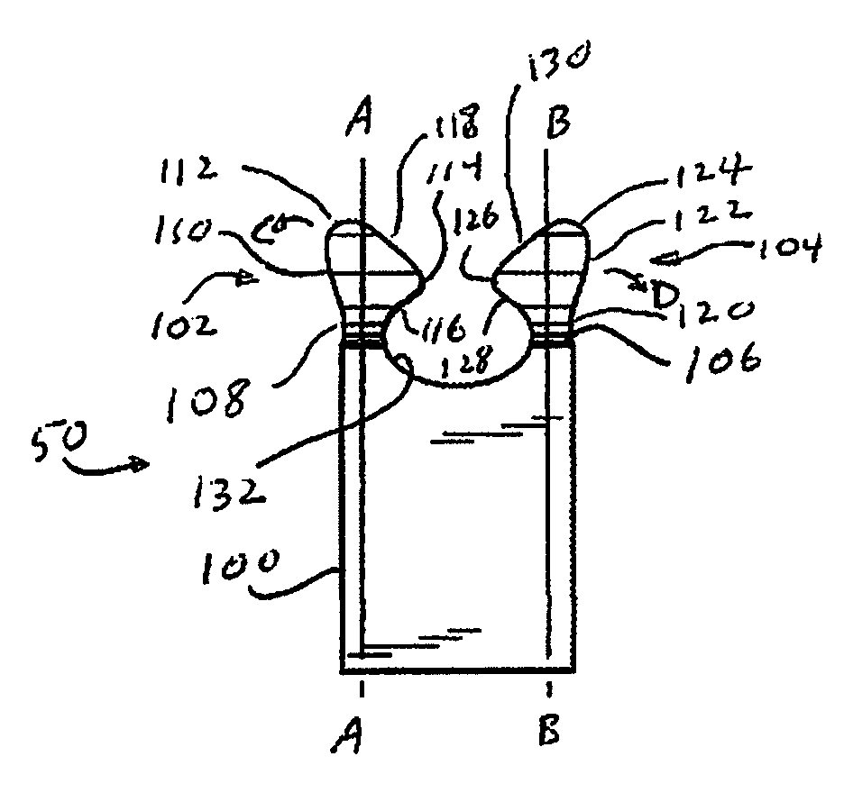
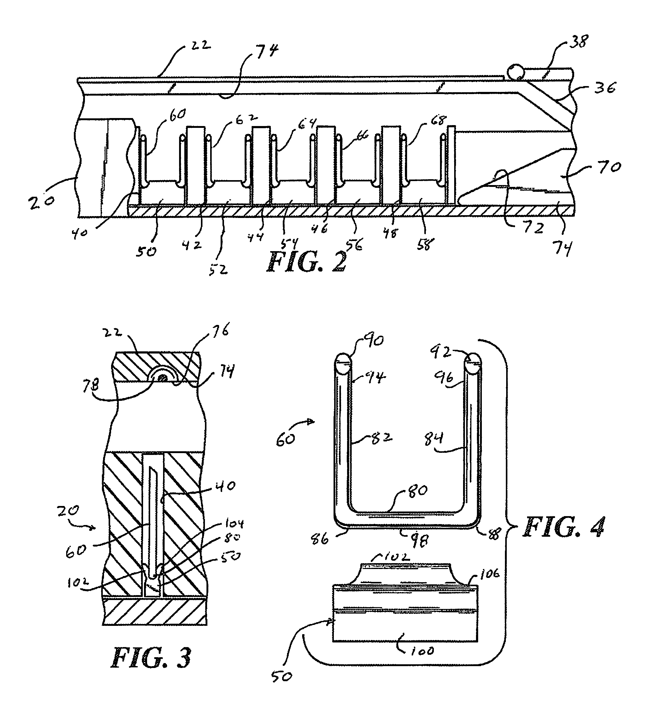
The patent text describes a staple cartridge for a surgical stapling instrument and a staple pusher for use with the cartridge. The staple cartridge includes a body with a staple pocket and a removable staple disposed therein. The staple pusher has flexible fingers with grasping projections that engage with the backspan of the staple. The staple pocket is partially defined by flared sidewalls to accommodate movement of the flexible fingers. The staple pusher has a partially rectangular body with longitudinally extending trough for support of the staple backspan. The staple pusher has at least three fingers, with one finger on each side of the body, or may have a fourth finger on the other side. The technical effects of the patent text include improved stability and flexibility of the staple pusher to facilitate use in a staple cartridge and improved engagement with the staple to ensure proper functioning of the surgical instrument.

Problems solved by technology

In this situation, the staples are subject to inadvertent complete or partial dislodgment out of the staple pockets during shipping and handling prior to use.
This situation may make it difficult or impossible to properly use the staple cartridge with a surgical stapling instrument during a surgical procedure.

Method used


Image

  • Loose staples removal system
  • Loose staples removal system
  • Loose staples removal system

Examples


Embodiment Construction

[0035]Embodiments of the presently disclosed staple pushers for use in a staple cartridge of a surgical stapler will now be described in detail with reference to the drawings wherein like numerals designate identical or corresponding elements in each of the several views. As is common in the art, the term “proximal” refers to that part or component closer to the user or operator, i.e. the surgeon or physician, while the term “distal” refers to that part or component further away from the user.

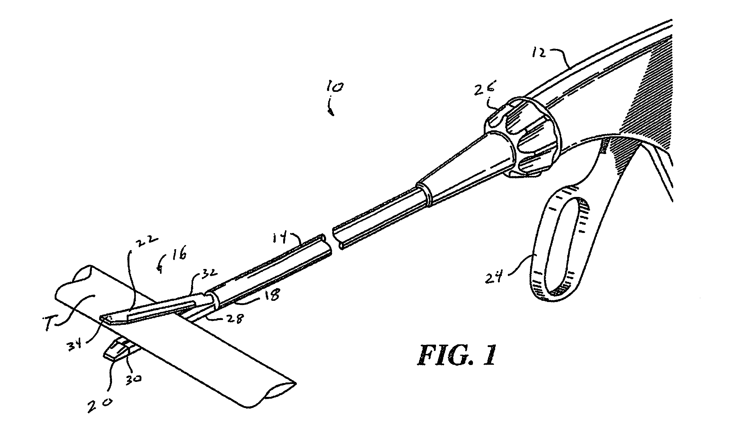
[0036]Referring initially to FIG. 1, there is illustrated a surgical stapler 10 for use in stapling a tubular tissue T. Surgical stapler 10 generally includes a handle portion 12 having an elongate tubular member 14 extending distally from handle portion 12. An end effector 16 is affixed to a distal end 18 of elongate tubular member 14 and generally includes a staple cartridge 20, removably affixed to distal end 18, and an anvil 22 movably mounted on distal end 18 of elongate tubular member 14....


PUM

PropertyMeasurementUnit
flexibleaaaaaaaaaa
widthaaaaaaaaaa
lengthaaaaaaaaaa

Abstract

A staple cartridge is provided for retaining fully formed staples not clenched through body tissue. The staple cartridge generally includes staple pockets containing surgical staples having a backspan and first and second legs projecting from the backspan and staple pushers positioned within the staple pockets beneath the surgical staples. The staple pushers include body portions having first and second flexible fingers extending from the body portions and removably engagable with the backspan of the surgical staples. The flexible fingers include flexible stems extending from the body portions and head portions extending from the flexible stems. Each head portion includes a rounded distal tip positioned offset from and outward of a central axis of the stem and an inwardly projecting grasping portion for engaging the backspan of the surgical staple. Distal ends of sidewalls of the staple pockets are flared outwardly to accommodate movement of the head portions of the flexible fingers.

Description

BACKGROUND[0001]1. Technical Field[0002]The present disclosure relates to a system for preventing fully formed loose staples from remaining in the body of a patient. More particularly, the present disclosure relates to a staple cartridge for use with a surgical stapling instrument and having structure for retaining and removing fully formed loose staples.[0003]2. Background of Related Art[0004]During certain surgical procedures it is often necessary to staple body tissue in order to join tissue sections or close tubular tissue sections to prevent leakage. This is typically accomplished by the use of a surgical stapling instrument having a staple containing cartridge and an anvil member movably mounted relative to the staple cartridge. Surgical staples are retained within pockets formed in the staple cartridge and blocks or pushers are mounted beneath the staple within the staple pockets. In use, tissue is positioned between the staple cartridge and the anvil and the anvil is moved a...

Claims


Application Information

Patent Timeline
Patent Type & Authority Patents(United States)
IPC IPC(8): A61B17/072A61B19/02
CPCA61B17/07207A61B19/0288A61B2017/07264A61B2017/07278A61B50/362
Inventor KOSTRZEWSKI, STANISLAW
Owner TYCO HEALTHCARE GRP LP
Learn More