
Method and apparatus for a multiple transition temperature implant

a technology of transition temperature and implant, which is applied in the field of human body implants, can solve the problems of complex devices, no description of multiple transition temperatures in the same device, and large changes in the shape of the implant formed from memory metal

Inactive Publication Date: 2014-08-19
FOX WILLIAM CASEY
View PDF185 Cites 1127 Cited by
  • Summary
  • Abstract
  • Description
  • Claims
  • Application Information

AI Technical Summary

Benefits of technology

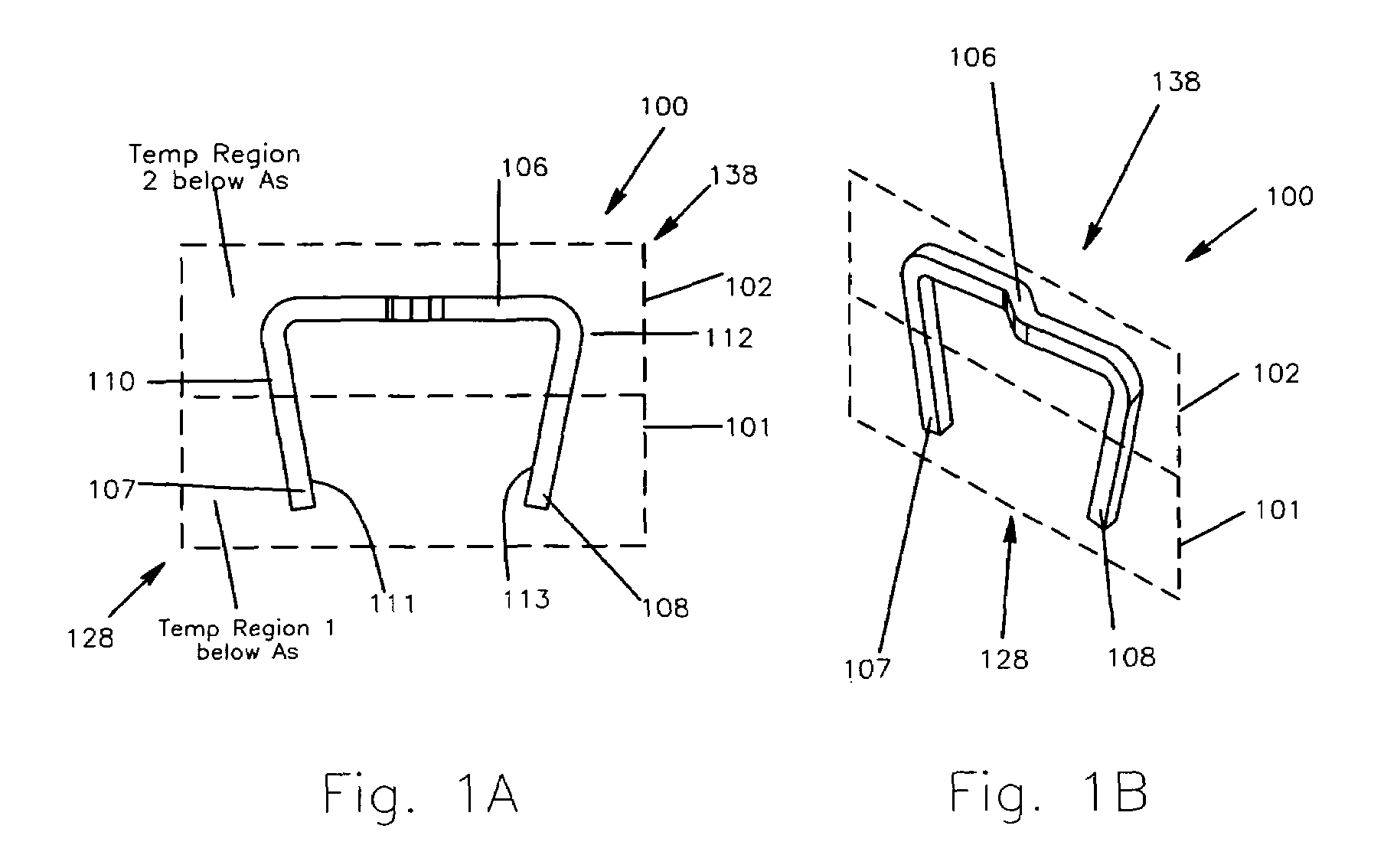
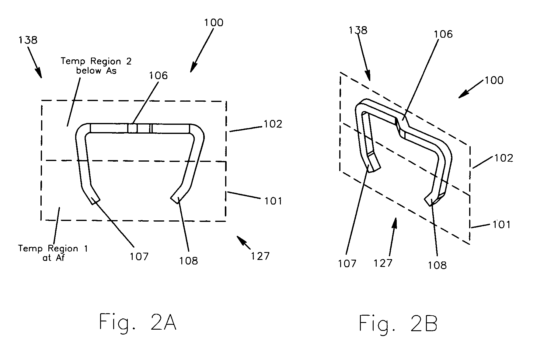
[0009]The present invention is a device made from a shape memory material that has the characteristic of having multiple transition temperatures. The presence of multiple transition temperatures allows shape changing devices to be designed that feature more complex shape changes, or shape changes that are applied in sequence. The present invention consists of methods for heat treating shape memory materials, and methods for attaching materials of different transition temperature characteristics.

Problems solved by technology

These heat-initiated changes cause gross changes in the shape of the implant formed from the memory metal.
Nevertheless, the implants and techniques in this patent do not describe multiple transition temperatures in the same device.
The existence of multiple transition temperatures would allow, for example, complex devices that can be heated first to one shape, and then heated further to additional shapes.

Method used


Image

  • Method and apparatus for a multiple transition temperature implant
  • Method and apparatus for a multiple transition temperature implant
  • Method and apparatus for a multiple transition temperature implant

Examples


first embodiment

[0095]In this alternative embodiment, the lower segments 161 and 163 are formed at a first transition temperature and the bridge 156 and upper segments 162 and 164 are formed at a second transition temperature. The lower segments 161 and 163 are then assembled together with the upper segments 162 and the bridge 156 to create the composite shape-memory device 150. In this specific example, the protrusions 167-168 are complementary in shape to the recesses 169-170, and of a size suitable for being press fit into a respective recess 169 or 170. Illustratively, the first protrusion 167 is press fit into the recess 169, and the second protrusion 168 is press fit into the recess 170, such that the contracting ends contract toward each other when moving from the second shape to the first shape, in similar fashion to the

[0096]FIG. 5D provides a flowchart illustrating the method steps for manufacturing the shape-memory device 150 according to this invention. The manufacturing process commenc...

second embodiment

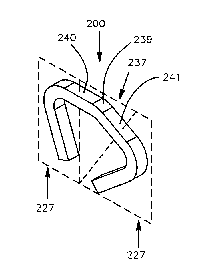
[0099]In a second embodiment, a shape-memory device 200 includes a first portion 201 having multiple zones, and a second portion 202 having a single zone. As shown in FIG. 6A, the first portion 201 includes a first zone 204 and a second zone 205 that have a first shape 227 and a second shape 228, and a first transition temperature. The second shape 228 is shown in FIGS. 6A-6B while the first shape 227 is shown in FIGS. 7A-7B. The second portion 202 includes a second shape 238, shown in FIGS. 7A-7B, and a first shape 237, shown in FIGS. 8A-8B, and a second transition temperature. In this example, the shape-memory device 200 is a staple that may be utilized as a surgical implant, and includes a first leg 207, a second leg 208, a bridge 206, a first bend 210, and a second bend 211.

[0100]In this second embodiment, the first bend 210 is disposed between the first leg 207 and the bridge 206, and the second bend 211 is disposed between the second leg 208 and the bridge 206. The first bend ...

third embodiment

[0116]Manufacturing of the shape-memory device 300 that includes multiple layers for independent activation requires the separate formation of each layer in the respective first shape, independent heat treatment to create a shape-memory profile, and bonding of the layers together. Illustratively, in this third embodiment the first portion 301 and the second portion 302 are welded together along the outer edges. As previously disclosed, each layer includes a first shape and a second shape, and may be worked from the first shapes to second shapes, thereby creating the ability to move from the second shape to the first shape upon the application of activation energy. While this shape-memory device 300 has been shown with the first portion 301 and the second portion 302 welded together, one of ordinary skill in the art will recognize that any form of suitable connection may be utilized to bond the layers to one another, including mechanical fasteners, adhesive bonds, and the like.

[0117]...


PUM


Abstract

A shape-memory device manufactured from shape memory material includes multiple activation temperatures. The multiple activation temperatures arise from either the heat treatment of the device during manufacturing, or by combining different elements with different activation temperatures. To manufacture a shape-memory device with multiple activation temperatures, it is formed into a first shape. A first portion of the shape-memory device is heated to a first temperature, and a second portion of the shape-memory device is heated to a second temperature. The shape-memory device is then worked into a second shape. Accordingly, the first portion has a first transition temperature, and the second portion has a second transition temperature. In use, the shape-memory device is placed into a desired position. Energy is applied such that the first portion, second portion, or both portions are transformed.

Description

BACKGROUND OF THE INVENTION[0001]1. Field of the Invention[0002]The present invention relates to implants for the human body and, more particularly, but not by way of limitation, to methods and an apparatus for an implant having multiple transition temperatures.[0003]2. Description of the Related Art[0004]Shape memory alloys such as nitinol have been well known since their development in 1965 by Buehler and Wiley (U.S. Pat. No. 3,174,851). Other metals, such as AuCd, FePt.sub.3, beta Brass, and InTI, exhibit shape memory behavior. These materials have the property of changing shape in response to a change in material temperature. This shape change potential is imparted into the memory metal device through a series of heat treatments.[0005]The transition temperature range is imparted to the material through varying mixtures of intermetallic compounds such as nickel-titanium and heat treatment. The heat treatment methods for the material generally consist of a high temperature setting...

Claims


Application Information

Patent Timeline
Patent Type & Authority Patents(United States)
IPC IPC(8): A61B17/56A61B17/84
CPCA61B17/0642A61B17/846A61B2017/00867A61F2/28A61F2210/0014A61B17/68A61B2017/0645A61B17/0644
Inventor FOX, WILLIAM CASEYPANCRATZ, DAVID JOSEPH
Owner FOX WILLIAM CASEY
Learn More