Implantation tools, tool assemblies, kits and methods

a technology of implant device and tool assembly, applied in the field of paranasal sinus conditions, can solve the problems of inability to adequately perform the surgery at home, no wide-spread success of surgical approaches, and the expected improvement of symptoms of current surgical interventions, so as to achieve the effect of effectively anchoring the implant device and improving the seating of the surface against the tissu

Active Publication Date: 2015-03-05
SINOPSYS SURGICAL
View PDF10 Cites 6 Cited by
  • Summary
  • Abstract
  • Description
  • Claims
  • Application Information

AI Technical Summary

Benefits of technology

The patent describes an implant device used in patients with fistulas. The device has protrusion areas on a portion of the conduit that will be placed within the fistula. These protrusion areas can help improve the device's ability to securely attach to the tissue and prevent leakage. The device is designed to make the device easier to insert and comfortable for patients. The protrusion areas can occur along a longitudinal portion of the conduit and may cover no more than a third of the conduit's area. This spacing between the protrusions allows for better tissue engagement and reduced likelihood of complications.

Problems solved by technology

Current surgical interventions may be expected to, at best, offer only moderate symptomatic improvement but no cure.
In addition to medication, frequent sinus irrigation can be helpful in flushing out debris, irritants and obstructing viscous fluids, but patients are generally not able to adequately perform this procedure at home.
None of these surgical approaches has achieved wide-spread success, and millions of chronic sinusitis patients continue to suffer long-term disability and discomfort.

Method used


Image

  • Implantation tools, tool assemblies, kits and methods
  • Implantation tools, tool assemblies, kits and methods
  • Implantation tools, tool assemblies, kits and methods

Examples


Embodiment Construction

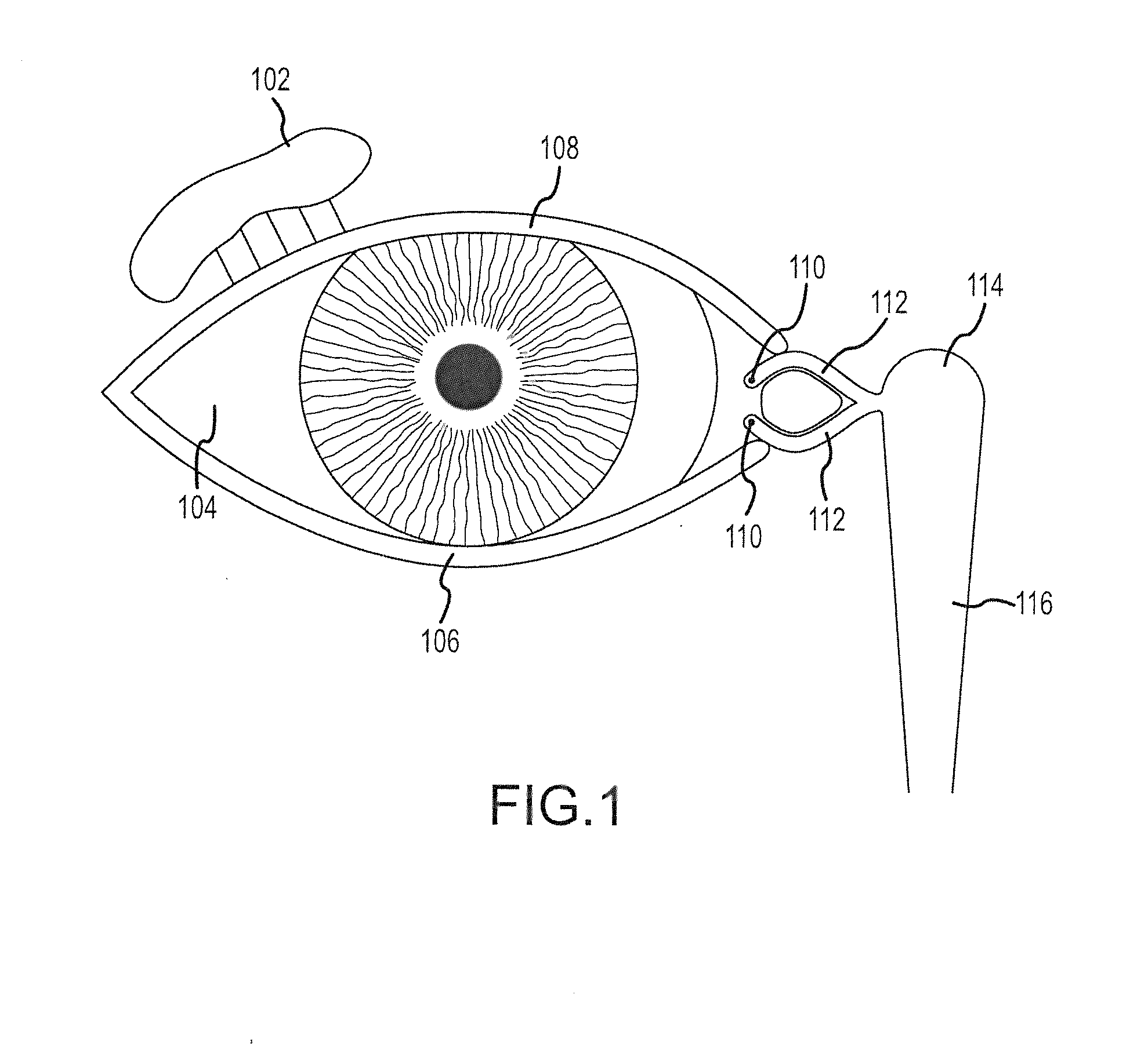
[0120]The terms “lacrimal apparatus” and “lacrimal system” are used interchangeably herein to refer to the collection of physiological components that accomplish the production and secretion of lacrimal fluid to lubricate the eyeball, containment of lacrimal fluid in a reservoir of lacrimal fluid in the orbit and drainage of lacrimal fluid from the orbit to the nasal cavity. The lacrimal apparatus includes the lacrimal glands, the tear drainage system and the reservoir of lacrimal fluid located between the lacrimal glands and the tear drainage system. The reservoir of lacrimal fluid includes the eyelid margins and the conjunctival sac (and including the pool of tears in the lower conjunctival cul-de-sac that is sometimes referred to as the lacrimal lake). The tear drainage system includes the puncta, canaliculi and nasolacrimal duct (including the so-called lacrimal sac located at the top of the nasolacrimal duct) through which excess tears drain to Hasner's valve and into the nasal...


PUM


Abstract

An implant device to provide an artificial fluid path in fluid communication with the lacrimal apparatus is implanted through a fistula opening into the lacrimal apparatus using a working member disposed through the implant device and a break-away sheath. Implantation kits and tool assemblies including the working member, implant device and break-away sheath facilitate implantation of the implant device.

Description

CROSS-REFERENCE TO RELATED APPLICATIONS[0001]This application claims a benefit of priority to U.S. provisional patent application No. 61 / 623,022 entitled “IMPLANTATION TOOL, TOOL ASSEMBLIES, KITS AND METHODS” filed Apr. 11, 2012.[0002]This application incorporates by reference each and every portion of the following: international patent application no. PCT / US2011 / 055456 entitled “IMPLANT DEVICE, TOOL, AND METHODS RELATING TO TREATMENT OF PARANASAL SINUSES” filed Oct. 7, 2011; U.S. nonprovisional patent application Ser. No. 13 / 225,213 entitled “IMPLANT DEVICE, TOOL, AND METHODS RELATING TO TREATMENT OF PARANASAL SINUSES” filed Sep. 2, 2011; U.S. provisional patent application No. 61 / 528,058 entitled “IMPLANT DEVICE, TOOL, AND METHODS RELATING TO TREATMENT OF PARANASAL SINUSES” filed Aug. 26, 2011; and U.S. provisional patent application No. 61 / 404,716 entitled “METHODS AND TOOLS FOR TREATMENT AND PREVENTION OF SINUSITIS” filed Oct. 8, 2010.FIELD OF THE INVENTION[0003]The invention r...

Claims


Application Information

Patent Timeline
IPC IPC(8): A61M27/00A61M29/00
CPCA61M27/002A61M2210/0681A61M29/00A61F9/00772A61B17/3468
Inventor ROSS, HARRYWILLOUGHBY, BRIAN JAMESOLIVER, CHRISTOPHER LEESCHOMER, DONALD F.CIMINO, WILLIAM W.
Owner SINOPSYS SURGICAL
Why Eureka
Try Eureka