
Diesel combustion system

a diesel fuel and combustion system technology, applied in the direction of combustion engines, charge feed systems, fuel re-atomisation/homogenisation, etc., can solve the problems of high diesel fuel consumption, low air utilization ratio, incomplete combustion, etc., to facilitate the formation of gas mixtures, increase the diffusion velocity of diesel fuel, and facilitate air entrainment

Inactive Publication Date: 2015-02-26
DALIAN UNIV OF TECH
View PDF14 Cites 12 Cited by
  • Summary
  • Abstract
  • Description
  • Claims
  • Application Information

AI Technical Summary

Benefits of technology

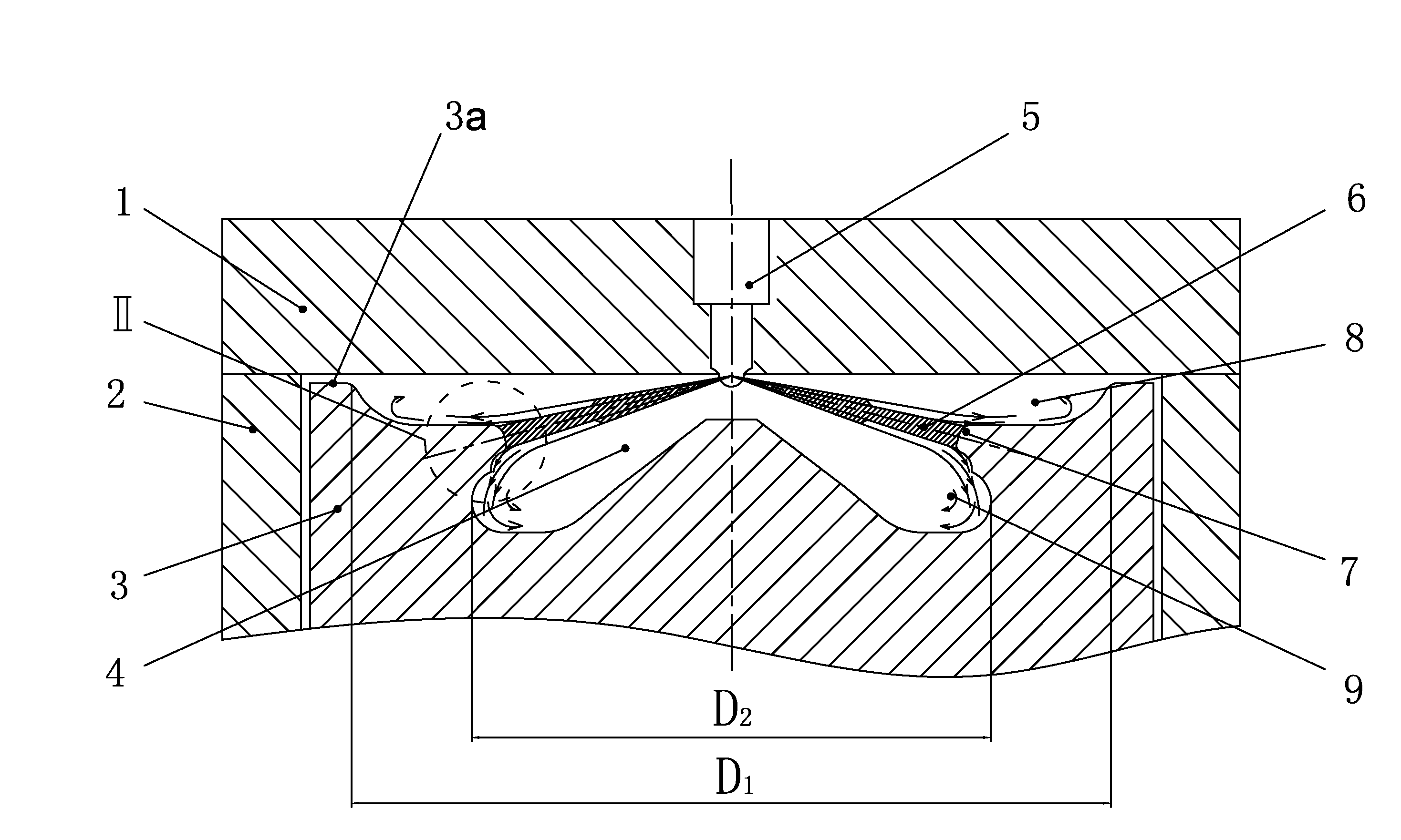
The invention is a diesel combustion system with a double-layered combustion chamber that improves fuel utilization and combustion performance. The system has an impinging block with an impinging surface and upper and lower guide surfaces. Part of the diesel fuel spray is rebounded and diffused along the guide surfaces, resulting in a double-layered split flow of the fuel. This prevents the accumulation of fuel near the point of fall and increases air entrainment, promoting better combustion performance and reducing fuel consumption and smoke emission.

Problems solved by technology

As a result, even if the diesel engine has a large excess air ratio, it has low air utilization ratio, incomplete combustion, high diesel fuel consumption, and high soot emission.

Method used


Image

  • Diesel combustion system
  • Diesel combustion system
  • Diesel combustion system

Examples


Embodiment Construction

[0035]For further illustrating the invention, experiments detailing a diesel combustion system comprising a double-layered combustion chamber are described below. It should be noted that the following examples are intended to describe and not to limit the invention.

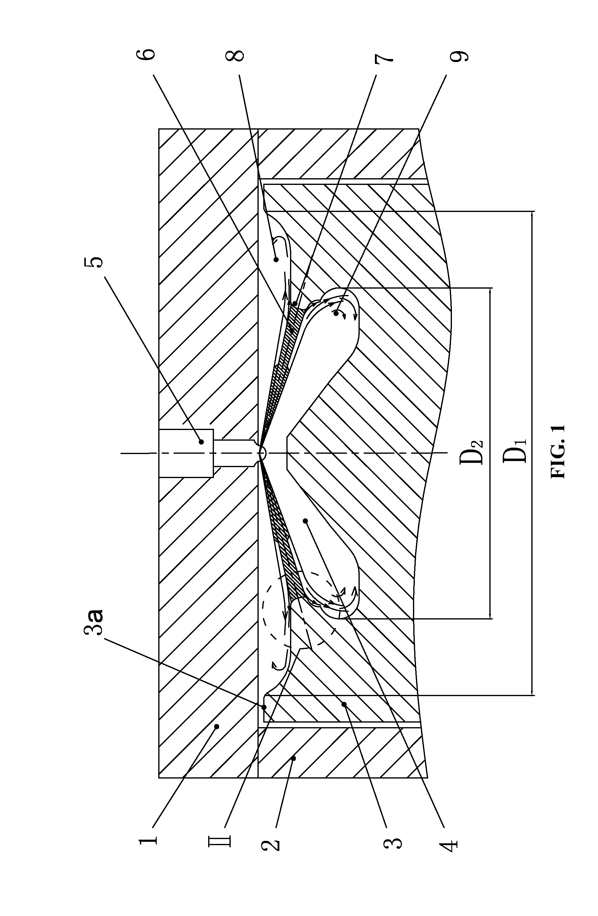
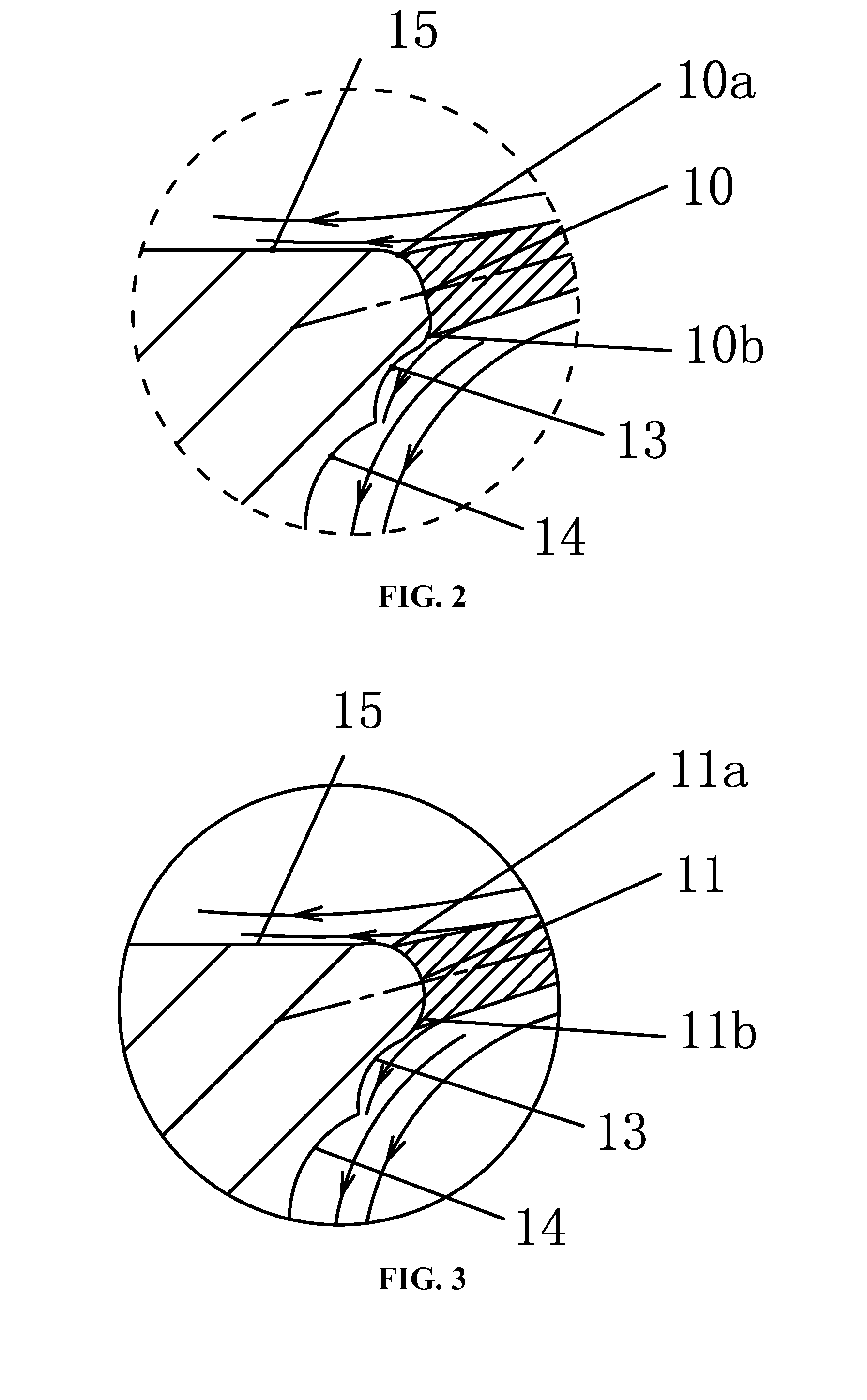
[0036]As shown in FIG. 1, a direct injection diesel combustion system comprises an injector 5 and a combustion chamber 4. The combustion chamber is formed by a cylinder head 1, a cylinder liner 2, and a piston 3. The injector 5 is configured to inject high pressure diesel fuel into the combustion chamber 4. The combustion chamber comprises an upper layer 8 and a lower layer 9, and a diameter D1 of the upper layer is larger than a diameter D2 of the lower layer. A junction of the upper layer and the lower layer is provided with an impinging block 7. The impinging block 7 comprises an impinging surface, an upper guide surface, and a lower guide surface. Part of the diesel fuel spray is rebounded by the impinging surface, an...


PUM


Abstract

A diesel combustion system including an injector and a combustion chamber. The combustion chamber is formed by a cylinder head, a cylinder liner, and a piston. The combustion chamber includes an upper layer and a lower layer. The diameter D1 of the upper layer is larger than the diameter D2 of the lower layer. A junction of the upper layer and the lower layer is provided with an impinging block for rebounding the diesel fuel spray. The impinging block includes an impinging surface, an upper guide surface, and a lower guide surface. When in use, part of the diesel fuel spray is rebounded by the impinging surface, and part of the diesel fuel spray is diffused along the upper guide surface and the lower guide surface of the impinging block to achieve double-layered split flow of the diesel fuel.

Description

CROSS-REFERENCE TO RELATED APPLICATIONS[0001]This application is a continuation-in-part of International Patent Application No. PCT / CN2013 / 000574 with an international filing date of May 15, 2013, designating the United States, now pending, and further claims priority benefits to Chinese Patent Application No. 201210152367.6 filed May 16, 2012. The contents of all of the aforementioned applications, including any intervening amendments thereto, are incorporated herein by reference. Inquiries from the public to applicants or assignees concerning this document or the related applications should be directed to: Matthias Scholl P.C., Attn.: Dr. Matthias Scholl Esq., 245 First Street, 18th Floor, Cambridge, Mass. 02142.BACKGROUND OF THE INVENTION[0002]1. Field of the Invention[0003]The invention relates to the mixture formation and combustion in an engine, and more particularly to a diesel combustion system comprising a double-layered combustion chamber.[0004]2. Description of the Relate...

Claims


Application Information

Patent Timeline
IPC IPC(8): F02M29/00F02F3/24F02B1/12
CPCF02M29/00F02F3/24F02B1/12F02B23/0651F02B23/0672F02B23/0693F02B2275/14F02B3/06Y02T10/12
Inventor LONG, WUQIANGQI, KUNPENGTIAN, JIANGPINGZHANG, QIANGSHENG, KAIYI, PINGWANG, YICONGFU, YAO
Owner DALIAN UNIV OF TECH
Learn More