
Quad flow torque enhancement flow divider causing improved fuel/air transfer

a flow divider and quadruple-flow technology, applied in the direction of liquid fuel feeders, combustion-air/fuel-air treatment, machines/engines, etc., can solve the problems of turbulence and corresponding drop in air velocity, and achieve superior fuel atomization, prevent mechanical and fluid flow interference, and increase fuel efficiency

Active Publication Date: 2015-02-26
PETERSON LONN M
View PDF50 Cites 1 Cited by
  • Summary
  • Abstract
  • Description
  • Claims
  • Application Information

AI Technical Summary

Benefits of technology

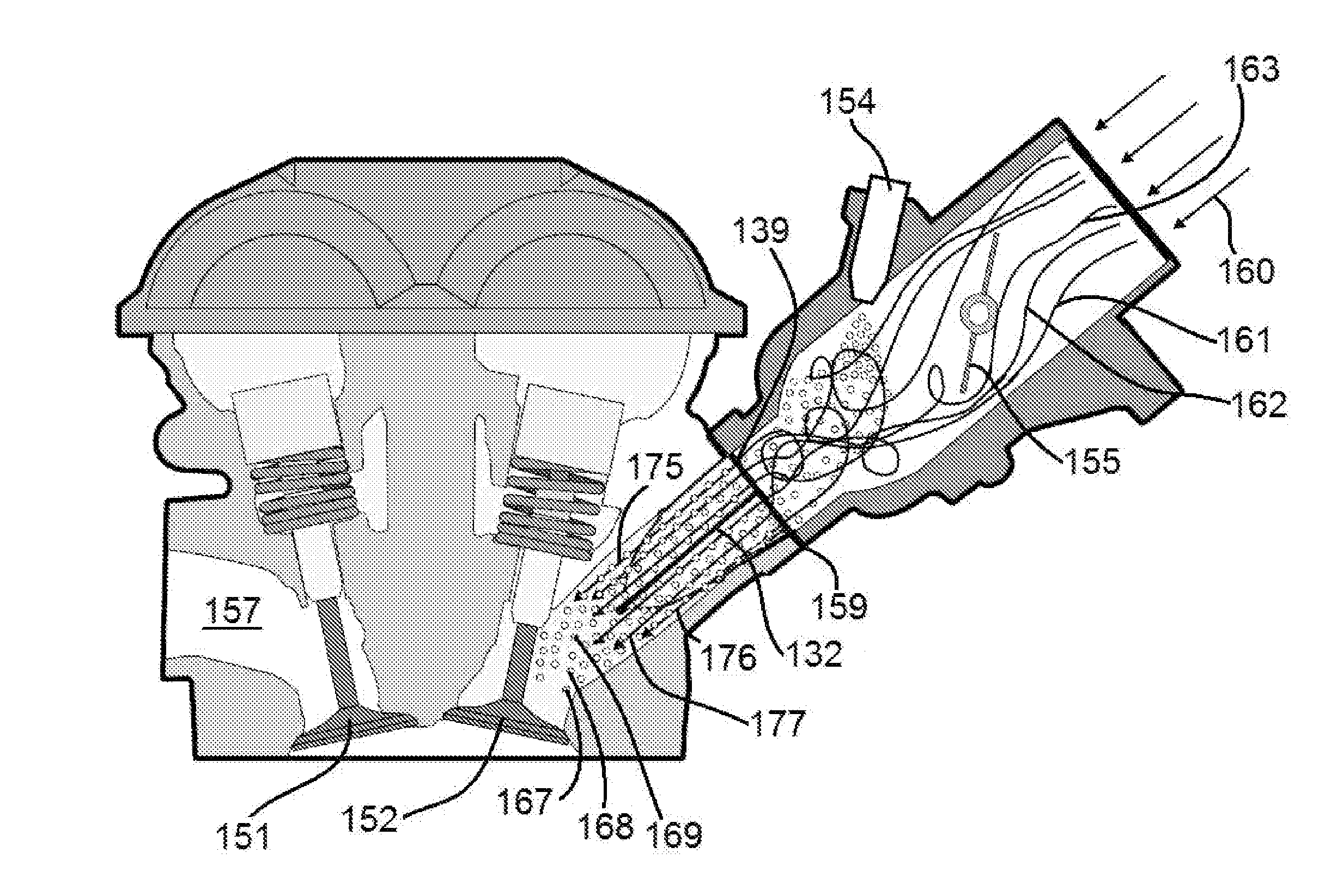
The present invention is a flow divider that reduces air turbulence in the carburetor, which improves fuel atomization and engine output power. It increases fuel efficiency and improves engine sensitivity to changes in fuel quality, temperature, and altitude. The invention results in increased fuel mileage and available engine power at a given throttle setting. It can be used in both two and four cycle engines.

Problems solved by technology

This velocity reduction is due to some portion of the air flow that passes under the carburetor slide being allowed to enter the full size of the carburetor bore, thereby producing turbulence and a corresponding drop in air velocity.

Method used


Image

  • Quad flow torque enhancement flow divider causing improved fuel/air transfer
  • Quad flow torque enhancement flow divider causing improved fuel/air transfer
  • Quad flow torque enhancement flow divider causing improved fuel/air transfer

Examples


Embodiment Construction

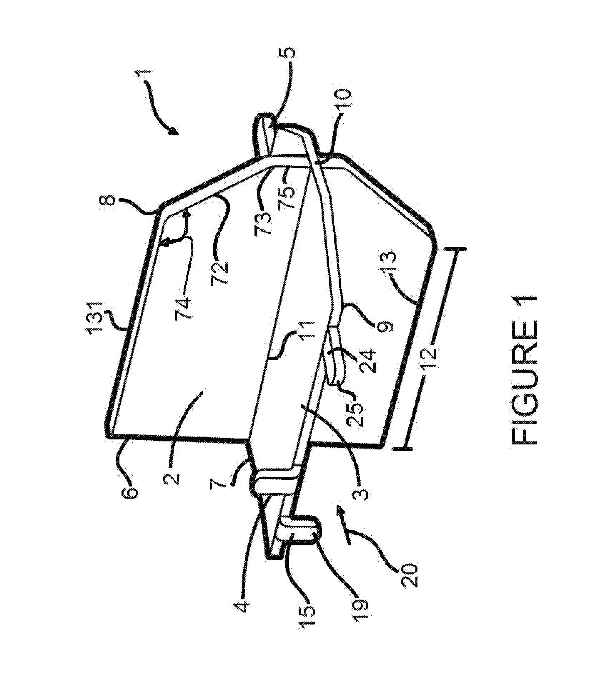
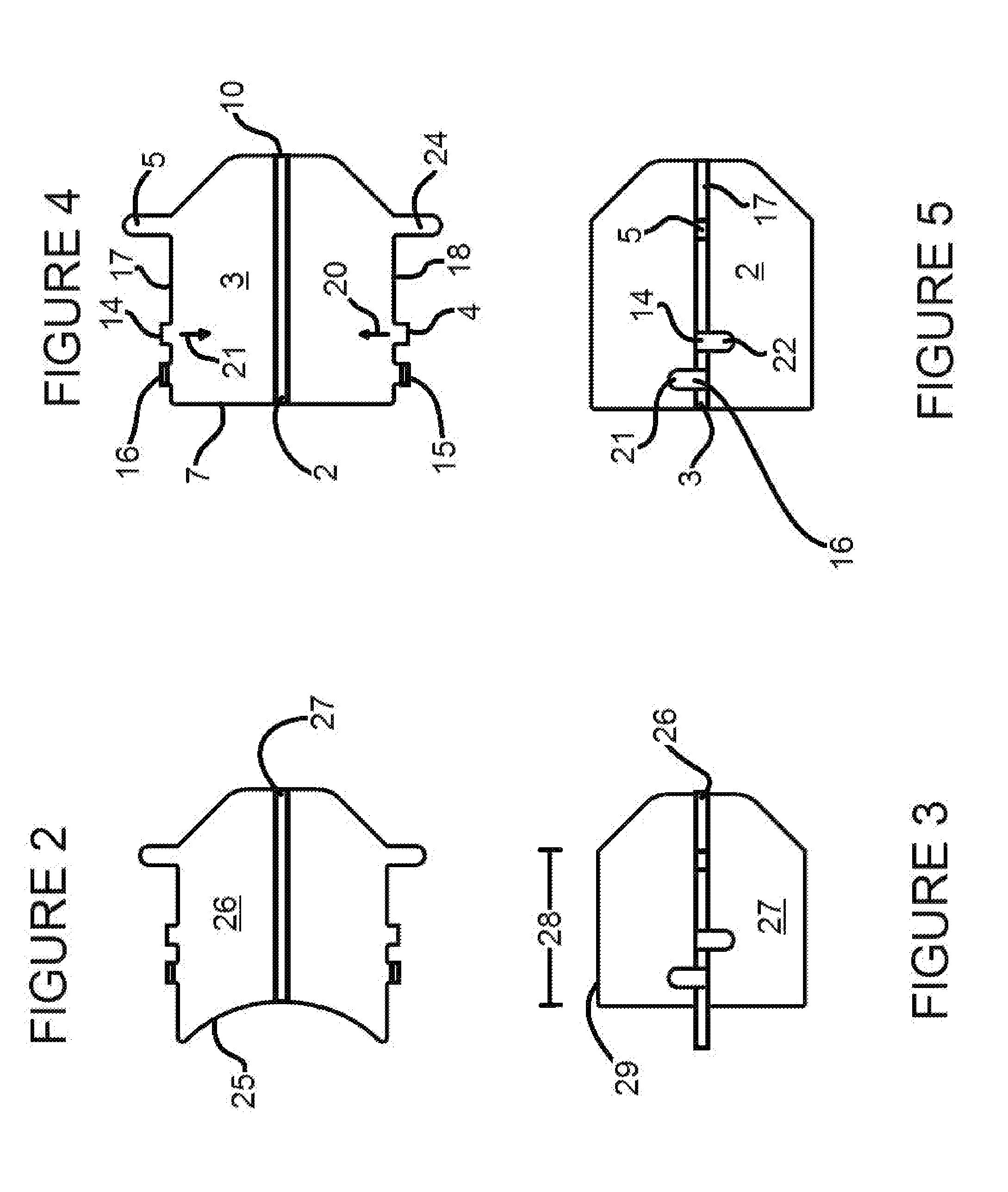
[0059]FIG. 1 depicts one embodiment of the torque wing 1 of the present invention. The torque wing 1 is formed to include a vertical plate 2 and a horizontal plate 3. Referring also to FIG. 6, the vertical plate 2 includes a centrally located slit 30 that terminates at orifice 31. Similarly, the horizontal plate includes a centrally located slit 32 which terminates at orifice 33. By aligning the two slits 30 and 32 and advancing the plate 2 until the orifices 31 and 32 abut, the two plates 2 and 3 create seam 11, thereby permitting the plates 2 and 3 to be rigidly affixed to each other by some convenient means such as welding or brazing. The torque wing 1 may also be formed by a molding or machining process. The plates 2 and 3 are positioned so as to be substantially orthogonal. The leading edge 6 of vertical plate 2 and the leading edge 7 of the horizontal plate 3 are substantially coplanar. The vertical plate 2 includes an upper edge 131 and a substantially parallel lower edge 13,...


PUM

PropertyMeasurementUnit
Lengthaaaaaaaaaa
Fractionaaaaaaaaaa
Distanceaaaaaaaaaa

Abstract

A wing (1) including a vertical plate (2) and a horizontal plate (3) is placed in the throat of a carburetor (41) or throttle body (93). The wing (1) is located adjacent to and downstream from the throttle valve (46, 94). The edges (6, 7, 13, and 131) are held in a spaced apart relationship from the carburetor wall (44) by locating tabs (4, 14, 15 and 16) which abut the wall (44). Securing tabs (5, 24) extend from the edges and grip a gasket or boot associated with an existing intake manifold. The wing (1) causes the air / fuel mixture exiting a carburetor to follow channelized parallel paths (78, 81 and 84) into the intake manifold.

Description

[0001]This patent application is based on Provisional Patent Application No. 61 / 699,293, filed on Sep. 11, 2012.FIELD OF THE INVENTION[0002]The present invention pertains generally to the field of carburetion and fuel injection, and more particularly to the transport of the fuel / air mixture.BACKGROUND OF THE INVENTION[0003]A carburetor or a fuel injector is a device that causes the creation of a mixture of fuel and air in a predictable and efficient ratio. In the case of a carburetor fuel is introduced into an air volume which is subsequently transported to the combustion space within a cylinder. In the case of a fuel injector the fuel is sometimes injected directly into the cylinder combustion space, but in other situations is injected into an air volume that is then sent to the cylinder as is typical with carburetion systems. In either case, the fuel / air ratio is dependent on throttle setting.[0004]Controlling airflow volume and velocity within a carburetor largely determines the ...

Claims


Application Information

Patent Timeline
IPC IPC(8): F02M35/10
CPCF02M35/10124F02M35/10019F02M19/08Y10T29/49231
Inventor PETERSON, LONN M.
Owner PETERSON LONN M
Learn More