
Three-dimensional television display

a technology of three-dimensional television and display, which is applied in the field of three-dimensional lcd display, can solve the problem of limited design to a small number of viewers

Inactive Publication Date: 2015-02-12
LIGHTHOUSE TECH +1
View PDF2 Cites 5 Cited by
  • Summary
  • Abstract
  • Description
  • Claims
  • Application Information

AI Technical Summary

Benefits of technology

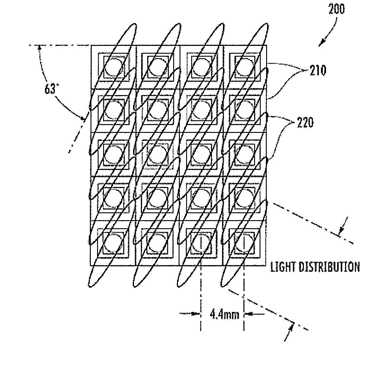
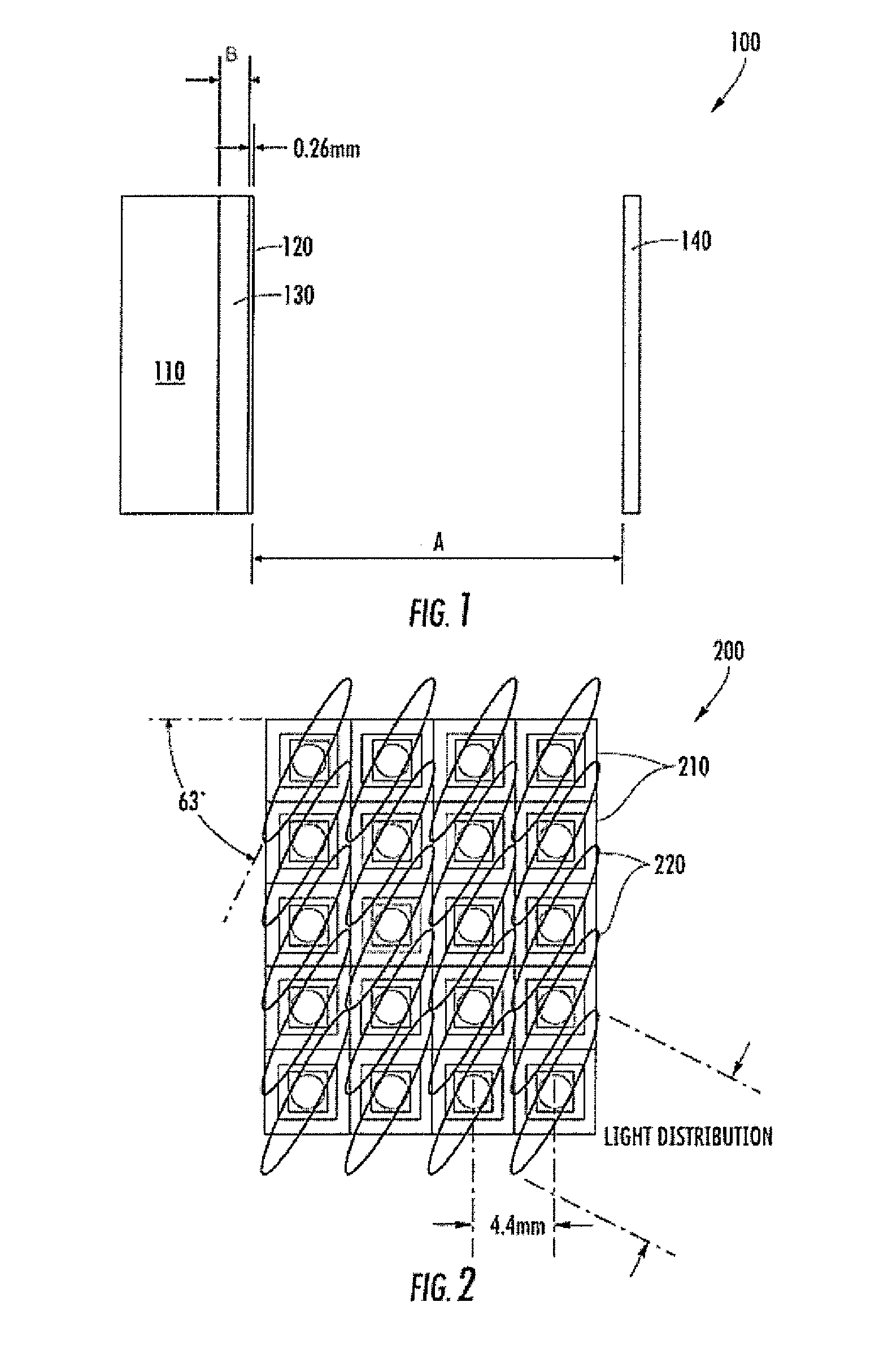
The present invention is a three-dimensional television display that uses a LED screen and a lenticular lens to distribute light emitted from the LED screen to a viewer's eyes. A parallax barrier is positioned between the lenticular lens and the viewer, with slits in the barrier transmitting the distributed light to the viewer's eyes. The lenticular lens is designed to have a center axis that is offset between 0° and 90° from the horizontal plane of the display screen. The distance between the lenticular lens and the viewer is substantially equal to the viewer's viewing distance divided by 15. The lenticular lens has a thickness that is dependent on the pixel pitch of the light sources. The light sources are light emitted diodes. The parallax barrier has slits that extend in a diagonal direction. The method of generating a three-dimensional image from the perspective of the viewer involves emitting light from the display screen, distributing it through the lenticular lens, and selectively transmitting portions of the distributed light through slits in the parallax barrier to the viewer's eyes. The size of the slits is determined by a reduction ratio. The invention provides a more immersive and realistic viewing experience for the viewer.

Problems solved by technology

From the point of view of the consumer, although the 3D glasses hardware for 3D display technology has developed significantly and also enables 3D images to be viewed by multiple viewers at the same time, this technology still suffers from a problem in which the viewers must wear special glasses to see the 3D images.
Yet, even as this technology progresses, the current state of the art still has many drawbacks.
For example, while conventional 3D LCD televisions have good resolution (e.g., 0.5 mm dot pitch) and provide a better 3D view by utilizing, for example, multiple parallax barriers, such designs are limited to a small number of viewers.

Method used


Image

  • Three-dimensional television display
  • Three-dimensional television display
  • Three-dimensional television display

Examples


Embodiment Construction

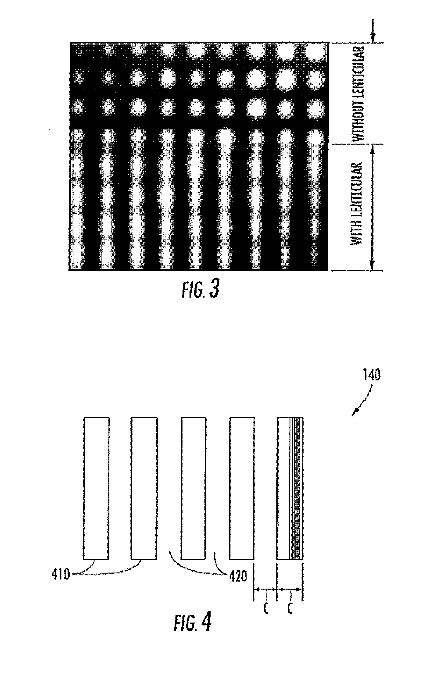
[0035]FIG. 1 illustrates a side view of 3D display device 100 according to an exemplary embodiment of the present invention. As can be seen in FIG. 1, the 3D display device 100 comprises an LED display 110, a lenticular sheet 120, a polycarbonate board 130 and a parallax barrier 140. In the exemplary embodiment, the LED display 110 itself is a conventional LED screen having a plurality of LED arrays with LED chips behind the television screen. The LED chips in one embodiment are surface mount RGB LEDS. One or more of the LEDs from the LED arrays are driven together to form pixels (e.g., a cluster of red, green, and blue diodes are driven together to form a full-color pixel). As will be discussed in more detail below, the lenticular sheet 120 and the parallax barrier 140 are provided to filter and separate each of the pixels to create the effect of a 3D image for a viewer.

[0036]As further shown, the 3D display device 100 further comprises a lenticular sheet 120 that is positioned adj...


PUM


Abstract

A three-dimensional television display including an LED screen having an array of light sources where the resolution of glass-less three-dimensional television display may be improved through the use of multiple LED array parallax, selection of the disposition of LED arrays in the multiple LED array parallax, a diagonal parallax barrier and lenticular lenses.

Description

TECHNICAL FIELD OF THE INVENTION[0001]The present invention relates to improvements in three dimensional LCD displays. More specifically, the resolution of glass-less three-dimensional television displays may be improved through the use of multiple LED array parallax, selection of the disposition of LED arrays in the multiple LED array parallax, a diagonal parallax barrier and lenticular lenses.BACKGROUND OF THE INVENTION[0002]Three-dimensional (“3D”) television is a developing technology for the consumer display market. Generally speaking, 3D television conveys depth perception to a viewer by employing various display techniques such as stereoscopic display, multi-view display, 2D-plus-depth, or any other form of 3D display. The basic technical requirement to achieve a 3D display is to display offset images that are filtered separately to the left eye and right eye.[0003]Conventionally, the primary technique to achieve a 3D display for a viewer is to require the viewer to wear eyeg...

Claims


Application Information

Patent Timeline
IPC IPC(8): G02B27/22G02B30/29G02B30/30
CPCG02B27/2214H04N13/31H04N13/317G02B30/30G02B30/29G02B30/27
Inventor KIKKAWA, SHINSAKUCHAN, KUI LAI CURIE
Owner LIGHTHOUSE TECH
Learn More