Plant pot with elevated ventilation hole

Inactive Publication Date: 2015-02-12
LEE BRET E +1
View PDF0 Cites 19 Cited by
  • Summary
  • Abstract
  • Description
  • Claims
  • Application Information

AI Technical Summary

Benefits of technology

The present invention is a plant pot with an Elevated Ventilation Hole (EVH) that provides better air circulation for plant roots, promoting faster plant growth. The pot has only one ventilation section, which is made in a conical shape, allowing multiple pots to be stacked on top of each other, saving storage space and transportation costs.

Problems solved by technology

Many people have found that traditional planting pots are not good enough for plants to grow well.
Because of this hole, very limited water can be retained and vital plant nutrition will be stripped away with each watering.
Many people find it is not an easy task.
However, since the base container is very shallow, the amount of water that can be kept therein is limited and will not be sufficient to keep the pot soil wet enough for healthy root development.
Over time, the upper portion of the pot soil will dry out and plants will not get enough water to grow.
This situation is very unfavorable for the plants, especially during the early stage of trans-plantation when plants are small and the roots are still weak and not long enough to reach the bottom of the pot.
Trans-planted plants could die from drought even if the base container still has water in.
Nevertheless, such access is restricted and there is difficulty in pouring the water therein.
Besides the inconvenience, the manufacturing cost is also increased because of its complicated design.
Nevertheless, the flower pot 110′ as described in U.S. Pat. No. 5,638,638 has a relatively complicated structure, which is difficult to manufacture and increases the cost thereof.
The excess of cylinders increases the materials needed and manufacturing cost.
However, too much water accumulated in the bottom portion of the plant pot may impede the air from circulating in and out of the plant pot and thus damage the plant roots, e.g. causing the roots to rot.
In this circumstance, the plant growth will be adversely affected.
However, the depth of the bottom reservoir is shallow and will only be able to reserve a small amount of water.
With a dozen holes on the bottom, it will not be able to hold the soil well.
Loss of soil may happen during watering or when moving the pot.
It is also difficult to enable the air to circulate in and out of the bottom of the plant pot when the water level accumulated in the lower portion of the pot is higher than the bottom of the pot.
In this regard, the plant roots may not get both sufficient water and air at the same time.
If both the top and bottom soils in a plant pot dry much faster than the soil in the center section of the pot, it results in an unnatural condition for the development of the plant roots.
Another problem is that, when water flows through the soil and out of the plant pots, the vital minerals and nutrients contained in the soil will be stripped with each watering.
While the above mentioned patented designs improved some functions of traditional pots, they created other problems.
Their complicated designs increase manufacturing costs by using more materials and more processing procedures.

Method used


Image

  • Plant pot with elevated ventilation hole
  • Plant pot with elevated ventilation hole
  • Plant pot with elevated ventilation hole

Examples


first embodiment

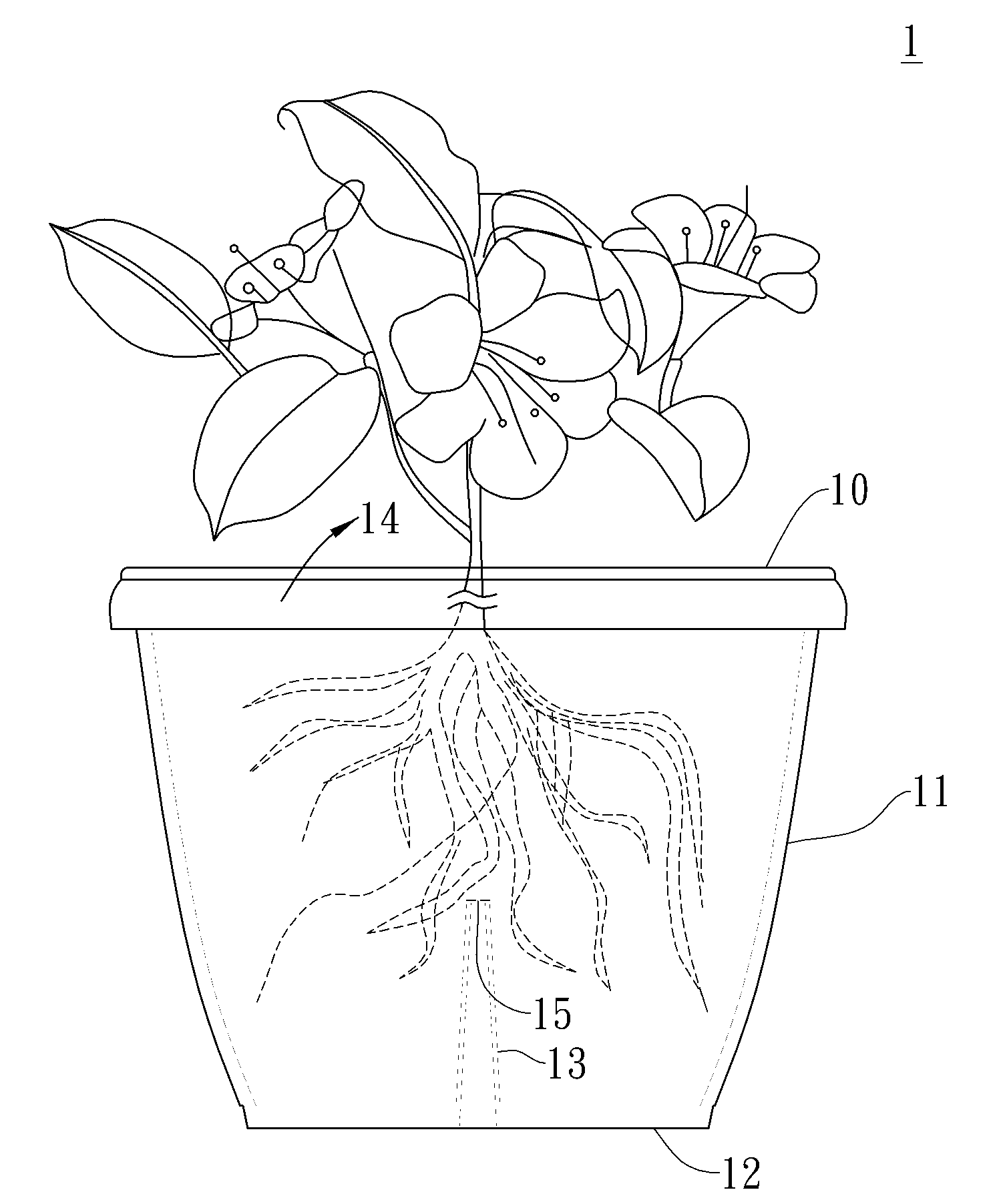
[0035]FIGS. 4A to 4C are schematic representation views showing a plant pot in accordance with the present disclosure. In this embodiment, referring to FIG. 4A, the plant pot 1 is constructed by a pot section 10, which has a truncated conical shape. The pot section 10 is constructed by a side wall 11 and a bottom wall 12. The side wall 11 is extending from and surrounding the bottom wall 12, such that the side wall 11 and the bottom 12 together define an accommodation space 14 for receiving soil, water and plants therein.

[0036]As shown in FIG. 4A, the bottom wall 12 is provided with a ventilation section 13 extending from the bottom wall 12 and toward the inside of the accommodation space 14. The ventilation section 13 is hollow, and is initially, e.g. upon being manufactured with an open hole or an enclosed end, at a height, H, which is smaller than that of the side wall 11, distal to the bottom wall 12. In some embodiments, the distal end 131 of the ventilation section 13 is eithe...

third embodiment

[0043]FIG. 6 shows a schematic representation view of a plant pot in accordance with the present disclosure. The plant pot 3 of this embodiment is similar to the one as shown in FIGS. 4A to 4C. The plant pot 3 comprises a ventilation section 33 has a cylindrical shape. The plant pot 3 further includes a water collecting reservoir 37 positioned at the bottom of the plant pot 3 for collecting excess water flowing out of the plant pot 3 through the ventilation hole 35 when water is poured into the plant pot 3.

[0044]Compared to the conventional plant pots, the present disclosure provides an environment and condition more similar to those in nature, in such a way that the moisture of the soil increases as it gets deeper, while the soil in traditional plant pots dry faster on both the top and at the bottom because both ends are exposed to the air.

[0045]The present disclosure is able to preserve more water in the pot than traditional ones, resulting in less watering frequency is needed in ...


PUM


Abstract

A plant pot with Elevated Ventilation Hole (EVH) comprises a pot section having a bottom wall and a side wall surrounding and connected to the bottom wall, the bottom wall and the side wall together defining an accommodation space for accommodating soil and plants, a bottom surface of the bottom wall having an inward recess portion with an adjustable height, the height being capable of manually adjusted to form a ventilation hole correspondingly, wherein a position of the ventilation hole corresponds to the adjustable height.

Description

TECHNICAL FIELD[0001]The present disclosure relates to plant pots. More particularly, the present disclosure relates to a plant pot with an improved structure that provides a more suitable environment for plant growth.DESCRIPTION OF RELATED ART[0002]Many people have found that traditional planting pots are not good enough for plants to grow well. For plants to grow well in pots, it is necessary to provide plants with sufficient air, water and nutrition. Traditional pots have a hole on the bottom, to provide air to the root of plants therein. Because of this hole, very limited water can be retained and vital plant nutrition will be stripped away with each watering. Therefore, potted plants need to be frequently cared for and watered in order to grow well. Many people find it is not an easy task.[0003]The growth of plants is highly influenced by the development of the roots. As recognized by the skilled person, one of the important factors which contribute to plant growth is the suffi...

Claims


Application Information

Patent Timeline
IPC IPC(8): A01G9/02
CPCA01G9/021A01G9/02
Inventor LEE, BRET E.LEE, JASON JEN SEN
Owner LEE BRET E
Why Eureka
Try Eureka