
Porous absorbent for sodium metal halide cells

a sodium metal halide and absorbent technology, applied in cell components, sustainable manufacturing/processing, batteries, etc., can solve the problems of reducing the charge capacity of sodium cell, reducing the cell life, and non-uniform distribution of liquid electrolyte throughout the cell cathode granule bed after frequent cycling

Active Publication Date: 2015-02-05
GENERAL ELECTRIC CO
View PDF3 Cites 8 Cited by
  • Summary
  • Abstract
  • Description
  • Claims
  • Application Information

AI Technical Summary

Benefits of technology

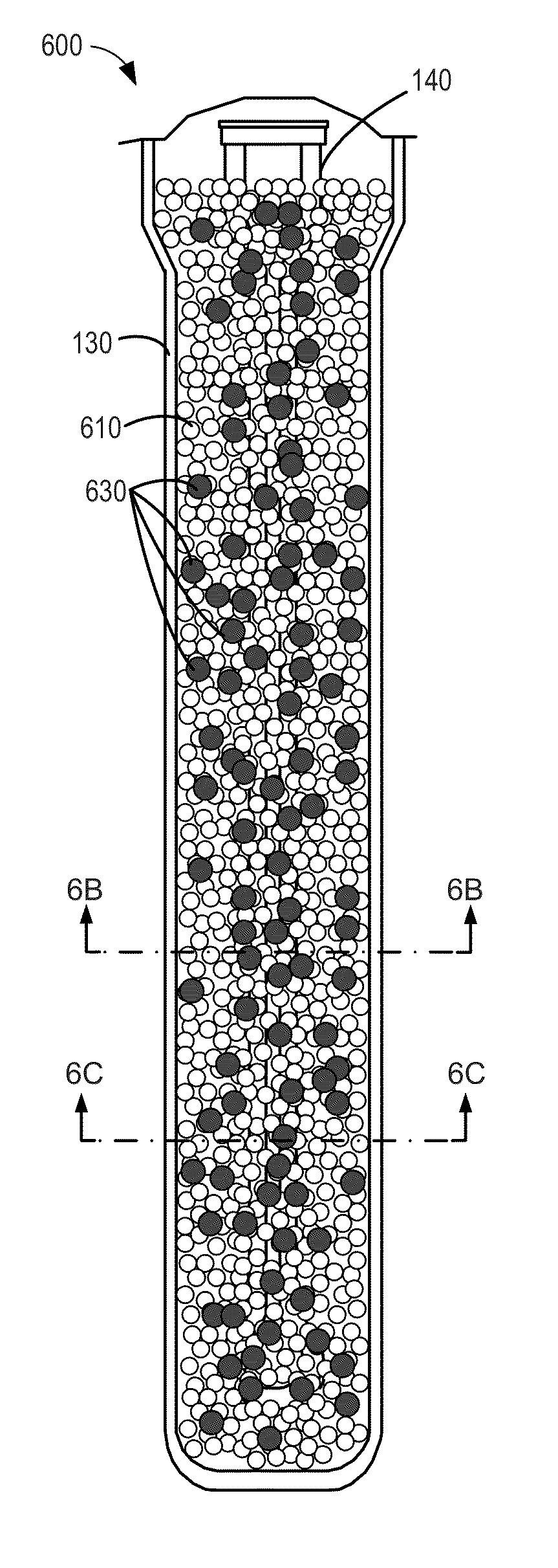
The patent describes a design for a battery cathode compartment that includes a porous absorbent material. The distribution of the absorbent material in the compartment is not uniform, but rather changes from one position to another. This design helps to maintain the uniform distribution of electrolyte throughout the compartment, which is important for the battery's performance and lifespan.

Problems solved by technology

One issue with sodium metal halide cells is that the distribution of liquid electrolyte throughout the cell cathode granule bed can become non-uniform after frequent cycling.
In particular, following many charge-discharge cycles, the cathode granule cathode bed particle morphology may change and / or degrade, developing heterogeneities such as regions of pore occlusion and channeling, thereby resulting in portions of the granule bed which are inaccessible to liquid electrolyte, and reducing the sodium cell charge capacity.
Furthermore, this granule bed degradation can worsen with successive cell cycling, significantly decreasing cell lifetime.
As such, the carbon felt slab structure reduces cross-communication (e.g., including transport of ions, electrons, and liquid electrolyte) between the isolated portions of the granule bed, thereby reducing charging and discharging efficiency during cell operation.
Furthermore, during manufacture of a sodium metal halide cell, the carbon felt slab structure may hinder uniform filling and distribution of the granule bed in the cathode compartment which can generate a load imbalance in the cell and further reduce cell operating efficiency.

Method used


Image

  • Porous absorbent for sodium metal halide cells
  • Porous absorbent for sodium metal halide cells
  • Porous absorbent for sodium metal halide cells

Examples


Embodiment Construction

[0034]The following description relates to various embodiments of a battery cathode compartment, also referred to herein as a cell cathode compartment, a battery, also referred to herein as a cell, and a method for preparing a cell compartment (e.g. a battery compartment).

[0035]In one embodiment, a cell cathode compartment may comprise a granule bed comprising metal granules, metal halide granules, and sodium halide granules. The cell cathode compartment may further include a liquid electrolyte dispersed in the granule bed, and a porous absorbent disposed in the granule bed, wherein a transverse cross-sectional distribution of the porous absorbent in the granule bed varies in a longitudinal direction from a first position to a second position. In this manner, distribution of liquid electrolyte throughout the granule bed can be maintained even after repeated charge-discharge cycles.

[0036]A longitudinal cross-section of a sodium metal halide cell 100 is shown in FIG. 1. The sodium met...


PUM

PropertyMeasurementUnit
thicknessaaaaaaaaaa
porosityaaaaaaaaaa
total volumeaaaaaaaaaa

Abstract

A cell cathode compartment comprises a granule bed comprising metal granules, metal halide granules, and sodium halide granules, a separator adjacent to the granule bed, a liquid electrolyte dispersed in the granule bed, and a porous absorbent disposed in the granule bed, wherein a transverse cross-sectional distribution of the porous absorbent in the granule bed varies in a longitudinal direction from a first position to a second position. In another embodiment, a cell cathode compartment comprises a granule bed comprising metal granules, metal halide granules, and sodium halide granules, a separator adjacent to the granule bed, a liquid electrolyte dispersed in the granule bed, and a porous absorbent coating on a surface adjacent to the granule bed.

Description

FIELD[0001]Embodiments of the subject matter disclosed herein relate to porous absorbent structures in sodium metal halide cells. Other embodiments relate to methods of preparing a sodium metal halide cell compartment.BACKGROUND[0002]Advanced batteries based on sodium metal halide chemistry (“sodium metal halide cells”) have been explored for use in electric vehicles, uninterruptable power systems (UPS), and telecom backup systems because of their high specific energy, power density, long cyclic life, and sustained high-power discharge over frequent cycling as compared to conventional lead-acid cells. One issue with sodium metal halide cells is that the distribution of liquid electrolyte throughout the cell cathode granule bed can become non-uniform after frequent cycling. In particular, following many charge-discharge cycles, the cathode granule cathode bed particle morphology may change and / or degrade, developing heterogeneities such as regions of pore occlusion and channeling, th...

Claims


Application Information

Patent Timeline
Patent Type & Authority Applications(United States)
IPC IPC(8): H01M10/39H01M10/38H01M4/38H01M4/58H01M4/04H01M4/36H01M50/466
CPCH01M10/399H01M4/048H01M4/364H01M4/38H01M2300/0057H01M4/0402H01M10/38H01M2220/20H01M2220/10H01M4/582H01M4/74H01M2004/028Y10T29/49115Y02E60/10Y02P70/50H01M50/466
Inventor RAMANI, MANIKANDANBALASCHAK, EDWARD JAMESGALLOWAY, ROBERT CHRISTIECOLE, RAYMOND R.BIELIK, JONATHAN ADAM
Owner GENERAL ELECTRIC CO
Learn More