
Liftable Hospital Bed

a hospital bed and lift technology, applied in nursing beds, transportation and packaging, surgery, etc., can solve the problems of affecting recovery, accompanied by continuous vibration, severe consequences, and discomfort of patients, and achieve the effect of reducing the power of electric motor, and gradually reducing the thrust mechanism

Active Publication Date: 2015-02-05
NINGBO KANGMAILONG MEDICAL APP
View PDF9 Cites 14 Cited by
  • Summary
  • Abstract
  • Description
  • Claims
  • Application Information

AI Technical Summary

Benefits of technology

This patent describes a hospital bed with a turnover mechanism that can lift the bed plate for easy movement. The mechanism uses connecting rods and a thrust mechanism to turn over the bed legs relative to the bed plate frame. This design allows for a gradual decrease in the force from the thrust mechanism, reducing the power needed and the cost of the electric motor. The bed's guide track is designed to closely attach the bed legs to the bed plate frame when the bed is at its lowest position, reducing thickness and storage space. Overall, this technology improves stability for patients during lifting and treatment, saves space, and reduces costs.

Problems solved by technology

As one end of the hospital bed is against the wall, all of the bed legs that are away from the wall are forced to move back, which is accompanied with continuous vibration.
Such a phenomenon typically results in discomfort to patients.
For a patient in severe condition who is inserted with a variety of tubes, in particular, the dragging caused by the movement of the hospital bed will result in severe consequences and affect recovery.
How to reduce the displacement of bed legs during lifting and to keep the patient posture and position steady has consistently been a difficult problem in this technical field.

Method used


Image

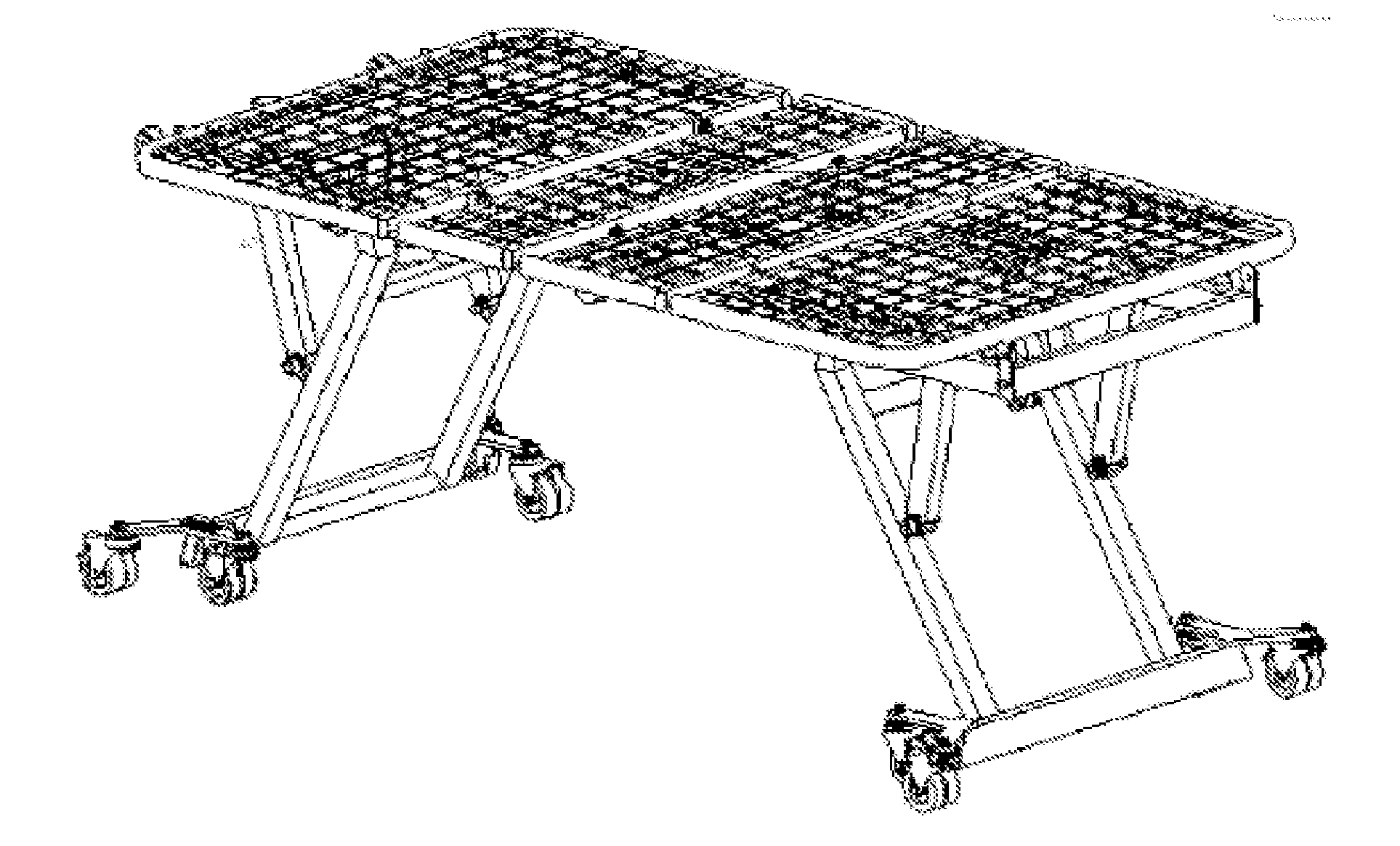
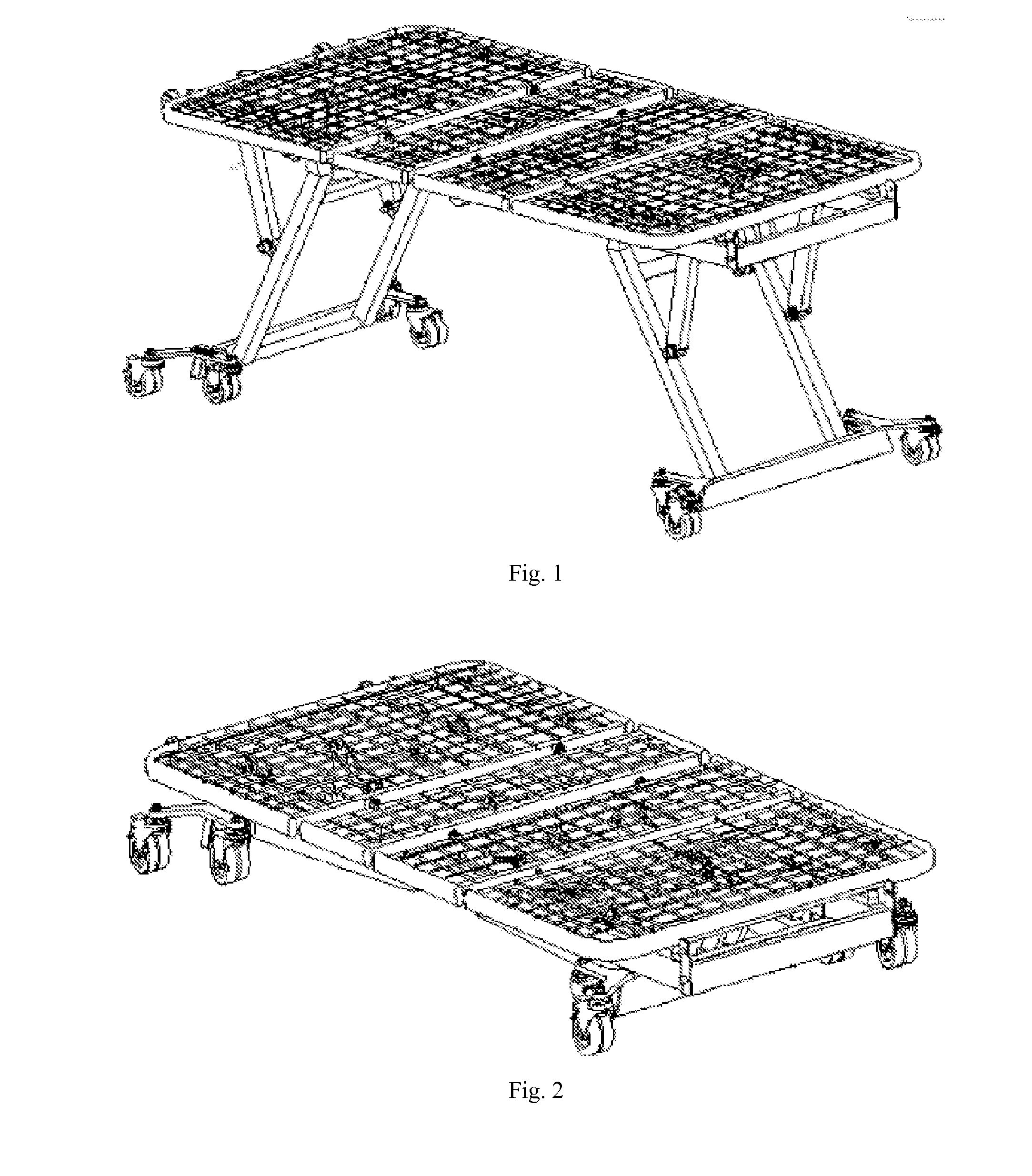
  • Liftable Hospital Bed
  • Liftable Hospital Bed
  • Liftable Hospital Bed

Examples


Embodiment Construction

[0025]The present invention will be further described below with reference to the accompanying drawings. Refer to the drawings:

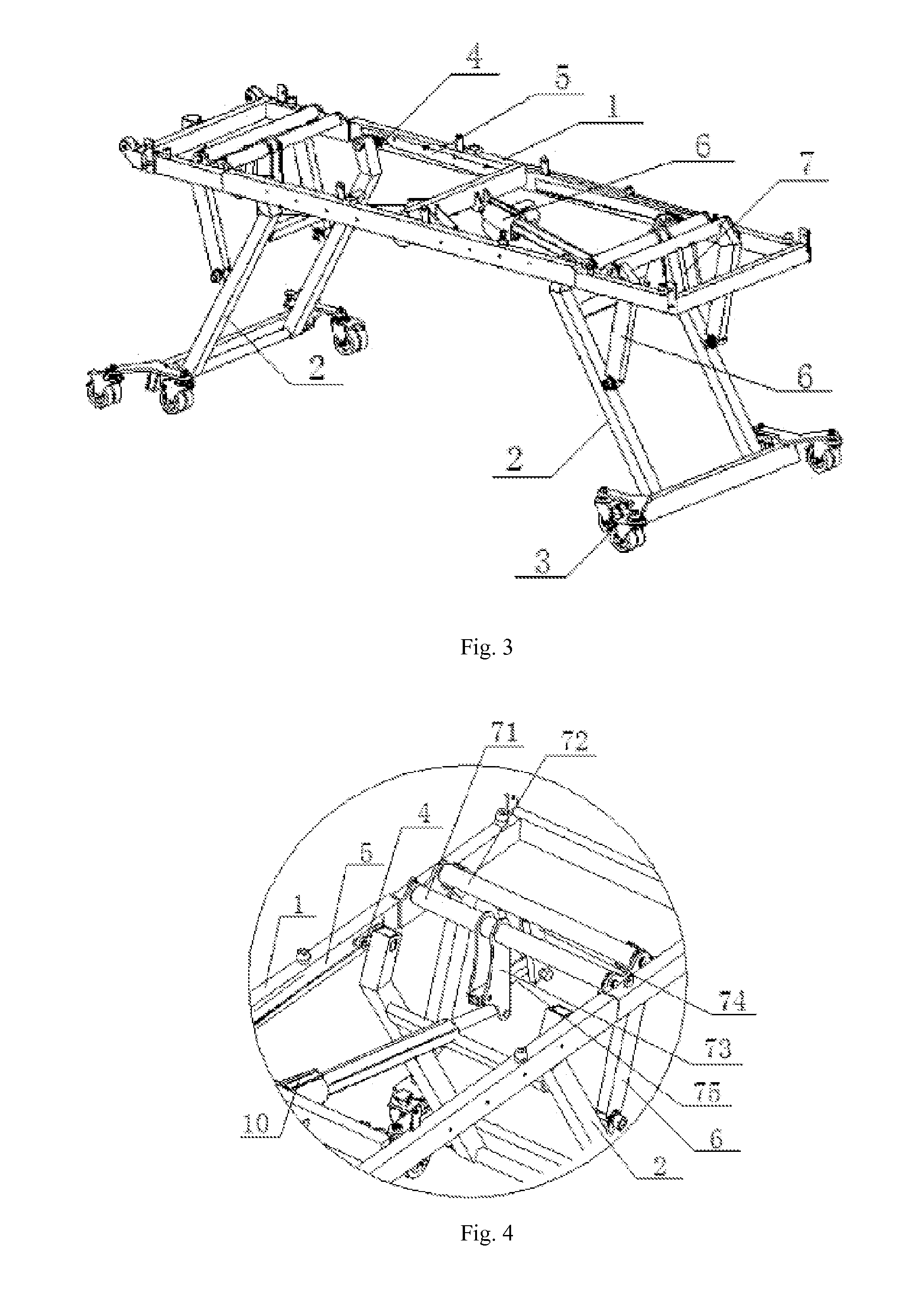
[0026]The liftable hospital bed according to the present invention comprises a bedplate base frame 1, the bedplate base frame 1 is symmetrical about a transverse central plane and a longitudinal central plane, two ends of the bedplate base frame 1 is provided with bed leg rods 2 and the lower end of the bed leg rods 2 are hinged to a first roller device 3 in contact with the ground, characterized in that:

[0027]The upper end of the bed leg rods 2 are connected to a second roller device 4, the second roller device 4 being slidable in tracks 5 on the bedplate base frame 1 and the tracks 5 being parallel to a longitudinal axis of the bedplate base frame 1;

[0028]Connecting rods 6 are hinged to the bed leg rods 2;

[0029]A turnover mechanism is further provided for changing the angles between the bed leg rods 2 and the bedplate base frame 1 to lift the bedplate base...


PUM


Abstract

Disclosed is a liftable hospital bed, comprising a bedplate base frame (1) symmetrical about a transverse central plane and a longitudinal central plane, wherein two ends of the bedplate base frame (1) are provided with bed leg rods (2), the lower end of the bed leg rods (2) being hinged to a first roller device (3) in contact with the ground and the upper end of the bed leg rods (2) being connected to a second roller device (4), the second roller device (4) being slidable in tracks (5) on the bedplate base frame (1) and the tracks (5) being parallel to a longitudinal axis of the bedplate base frame (1); connecting rods (6) are hinged to the bed leg rods (2); and a turnover mechanism is further provided for changing included angles between the bed leg rods (2) and the bedplate base frame (1) to lift the bedplate base frame (1), the turnover mechanism comprises the connecting rods (6) and a thrust mechanism, end portions of the thrust mechanism drive the connecting rods (6) to rotate via a hinged four-rod mechanism (7), and the connecting rods (6) drive the bed leg rods (2) to turn over relative to the bedplate base frame (1), so that the lifting of the hospital bed is realized.

Description

(I) FIELD OF THE INVENTION[0001]The present invention relates to a liftable hospital bed.(II) DESCRIPTION OF THE RELATED ART[0002]Regular hinge structures are employed between connecting rods and bed leg rods of existing hospital beds, the longitudinal displacement during the release and retraction of the bed leg rods cannot be compensated, and the ends of bed leg rods that touch the ground will change their longitudinal positions relative to the hospital bed. As a result, the entire hospital bed moves. As one end of the hospital bed is against the wall, all of the bed legs that are away from the wall are forced to move back, which is accompanied with continuous vibration. Such a phenomenon typically results in discomfort to patients. For a patient in severe condition who is inserted with a variety of tubes, in particular, the dragging caused by the movement of the hospital bed will result in severe consequences and affect recovery. Due to various reasons, however, a hospital bed mu...

Claims


Application Information

Patent Timeline
Patent Type & Authority Applications(United States)
IPC IPC(8): A61G7/012A61G7/018A61G7/015
CPCA61G7/012A61G7/018A61G7/015A61G1/0212A61G1/0562A61G7/005A61G13/04A61G13/06
Inventor LI, LUPING
Owner NINGBO KANGMAILONG MEDICAL APP
Learn More