
System and method of corner noise reduction in an image

a technology of corner noise and noise reduction, applied in the field of image noise reduction, can solve the problems of affecting the noise properties of digital images, affecting the image quality of the image, so as to reduce noise artifacts and not introduce too much complexity to the device hardwar

Inactive Publication Date: 2015-01-29
QUALCOMM INC
View PDF12 Cites 16 Cited by
  • Summary
  • Abstract
  • Description
  • Claims
  • Application Information

AI Technical Summary

Benefits of technology

The innovation described in this patent text is a way to reduce noise in digital images by using a special look up table to calibrate for changes in noise caused by vignetting. This method allows for effective noise reduction without complicated spatial processing and can be efficient and simple to apply to device hardware. The technical effect is the improved quality of digital images.

Problems solved by technology

Electronic noise is inherent to all captured electronic images, but its cause varies.
In cameras, light provided by the camera optics is often significantly reduced around sensor corners than the center, which is commonly known as “vignetting.” Spatial varying digital gain needs to be applied to compensate for the darkness in the corners, which is sometime referred to as “roll-off correction.” However, such spatial varying digital gain can distort the noise properties of an image and complicate the imaging noise reduction algorithms that are located behind roll-off correction step in the imaging pipeline.
This can be extremely costly to the ISP design.
This distortion can be caused by any processing modules that can introduce spatial varying digital gain such as roll-off correction, local tone mapping and the like.

Method used


Image

  • System and method of corner noise reduction in an image
  • System and method of corner noise reduction in an image
  • System and method of corner noise reduction in an image

Examples


Embodiment Construction

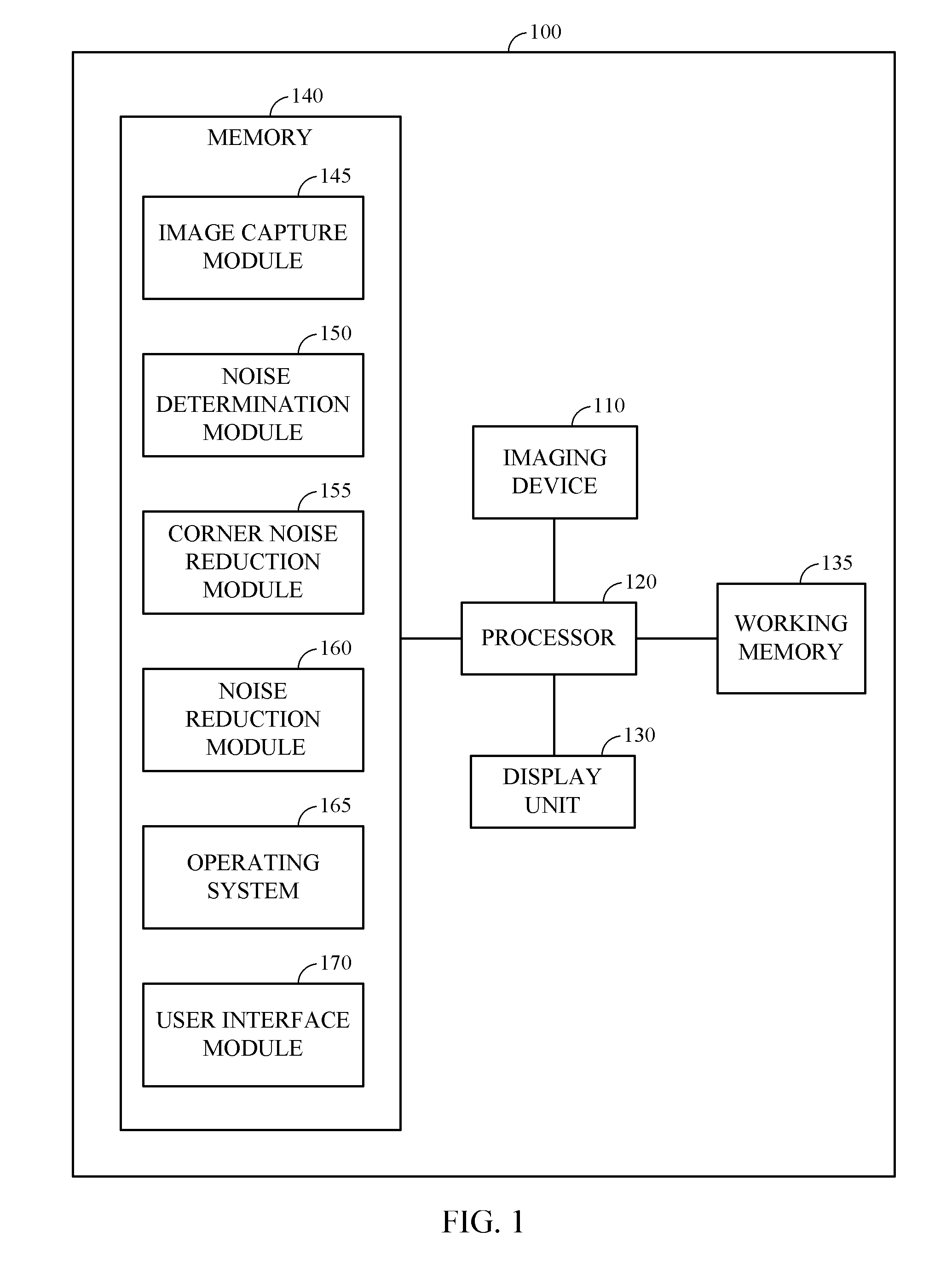
[0020]Many modules in an imaging pipe line of an electronic device may be (at least partially) dependent on an accurate model of noise that is in a captured image, and the modules may have built-in processes to handle any such imaging noise. Some examples of processes to handle certain types of imaging noise include, for example, de-speckle, non-linear filtering, median filtering, and adaptive image enhancement. Corner noise reduction (CNR) processes are designed to compensate for the non-stationary effect of noise caused by any spatial varying digital gain, typically affecting the corners of an image, without adding more complexities to existing noise reduction modules (e.g., to compensate for image vignetting). “Non-stationary noise” refers to noise in which the variance of the noise is spatially variant within the image. Specifically, the non-stationary noise effect can result in images with uncertain input data. For example, the variance of noise at the center of an image is rel...


PUM


Abstract

Systems and methods for reducing noise artifacts in an image are disclosed. A radial distance-based look up table may be used to calibrate a noise property change due to the vignette effect. Based on the look up table, a spatial varying noise reduction level is computed to correct the noise property distortion due to the image vignetting.

Description

RELATED APPLICATIONS[0001]This application claims the benefit of U.S. Provisional Application No. 61 / 858,901, filed Jul. 26, 2013, titled “SYSTEM AND METHOD OF CORNER NOISE REDUCTION IN AN IMAGE,” the disclosure of which is hereby incorporated by reference in its entirety.BACKGROUND[0002]1. Field of the Invention[0003]Embodiments relate to systems and methods of reducing noise artifacts in digital images. More specifically, embodiments relate to image noise reduction in the corners of a captured digital image.[0004]2. Description of the Related Art[0005]Electronic noise is inherent to all captured electronic images, but its cause varies. It is more apparent is some images, and barely noticeable in others. Higher ISO values will enhance this effect, as will underexposure or long exposure. Process over-sharpening will also enhance electronic noise. Some images may contain a combination of chromatic (color) and luminance (monochromatic) noise.[0006]In cameras, light provided by the cam...

Claims


Application Information

Patent Timeline
IPC IPC(8): G06T5/00
CPCG06T5/002G06T2207/20012H04N5/911H04N23/81H04N25/61G06T5/70H04N25/60
Inventor CHEN, YUNQIANGJIANG, XIAOYUN
Owner QUALCOMM INC
Learn More