Eureka AIR delivers breakthrough ideas for toughest innovation challenges, trusted by R&D personnel around the world.

Lighting device

Active Publication Date: 2015-01-29
HONDA MOTOR CO LTD
View PDF3 Cites 13 Cited by
  • Summary
  • Abstract
  • Description
  • Claims
  • Application Information

AI Technical Summary

Benefits of technology

The present invention provides a lighting device that can prevent a hand from approaching the heat sink during optical-axis adjustment. The invention includes a rib on the heat sink that reduces the likelihood of a hand reaching the fins. The design also includes an asymmetrical rib to save material and improve appearance. Additionally, the invention includes a steering handle lock mechanism to prevent accidental adjustments when accessing the lighting device. The lighting device supports the steering handle and is positioned in front of the forks, which reduces interspace between the device and the forks. The placement of the knob also improves operability.

Problems solved by technology

The lighting device described in Japanese Patent No. 4582791, however, does not have a structure devised to hinder such approach to the heat sink.
Thus, when a hand of an operator approaches the heat sink to turn the aiming adjustment knob, the hand is likely to touch the rib before it touches the heat sink.
Thereby, the operator can be aware that the heat sink is located nearby, which can hinder approach of the hand of the operator to the heat sink.

Method used


Image

  • Lighting device
  • Lighting device
  • Lighting device

Examples


Embodiment Construction

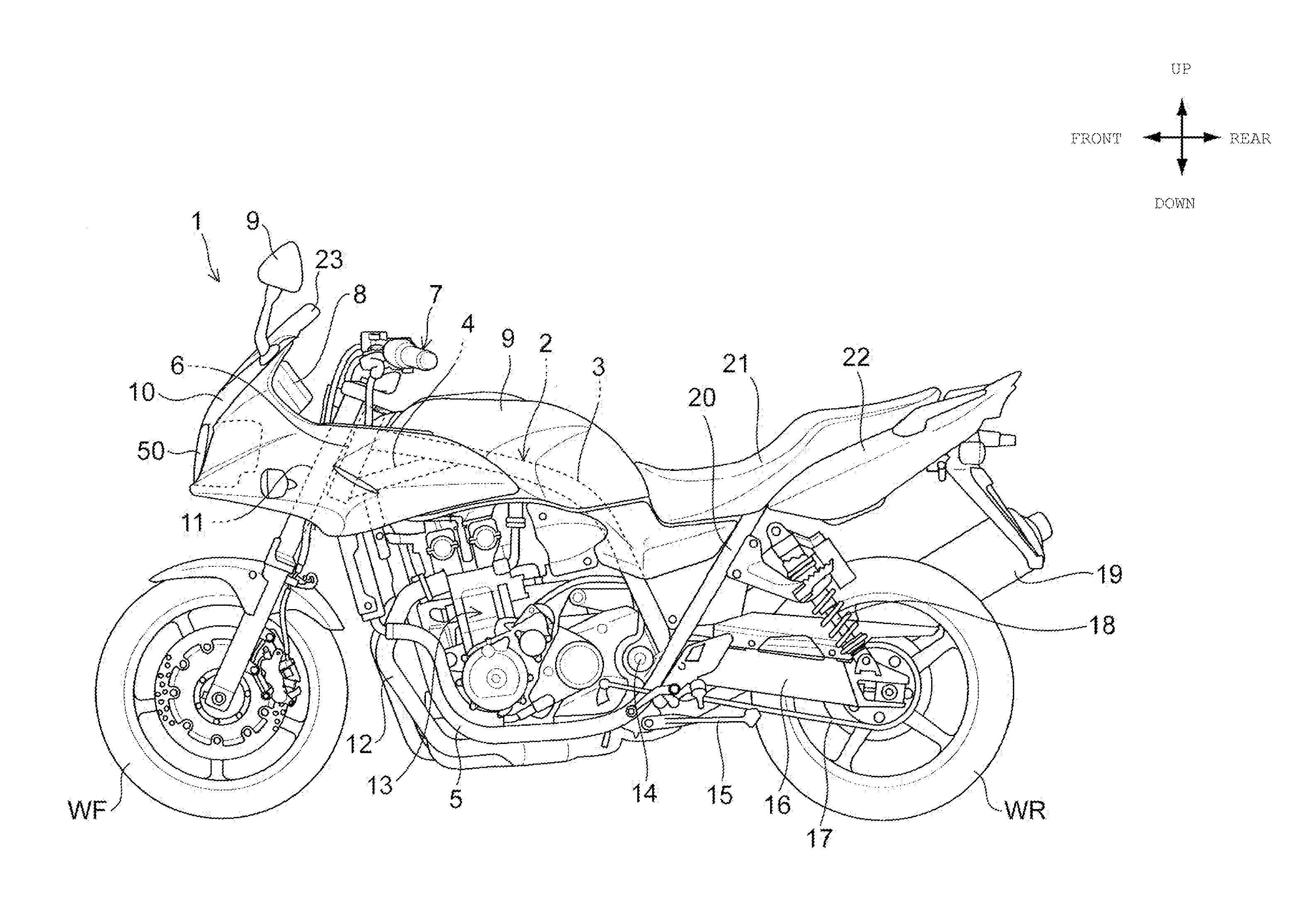
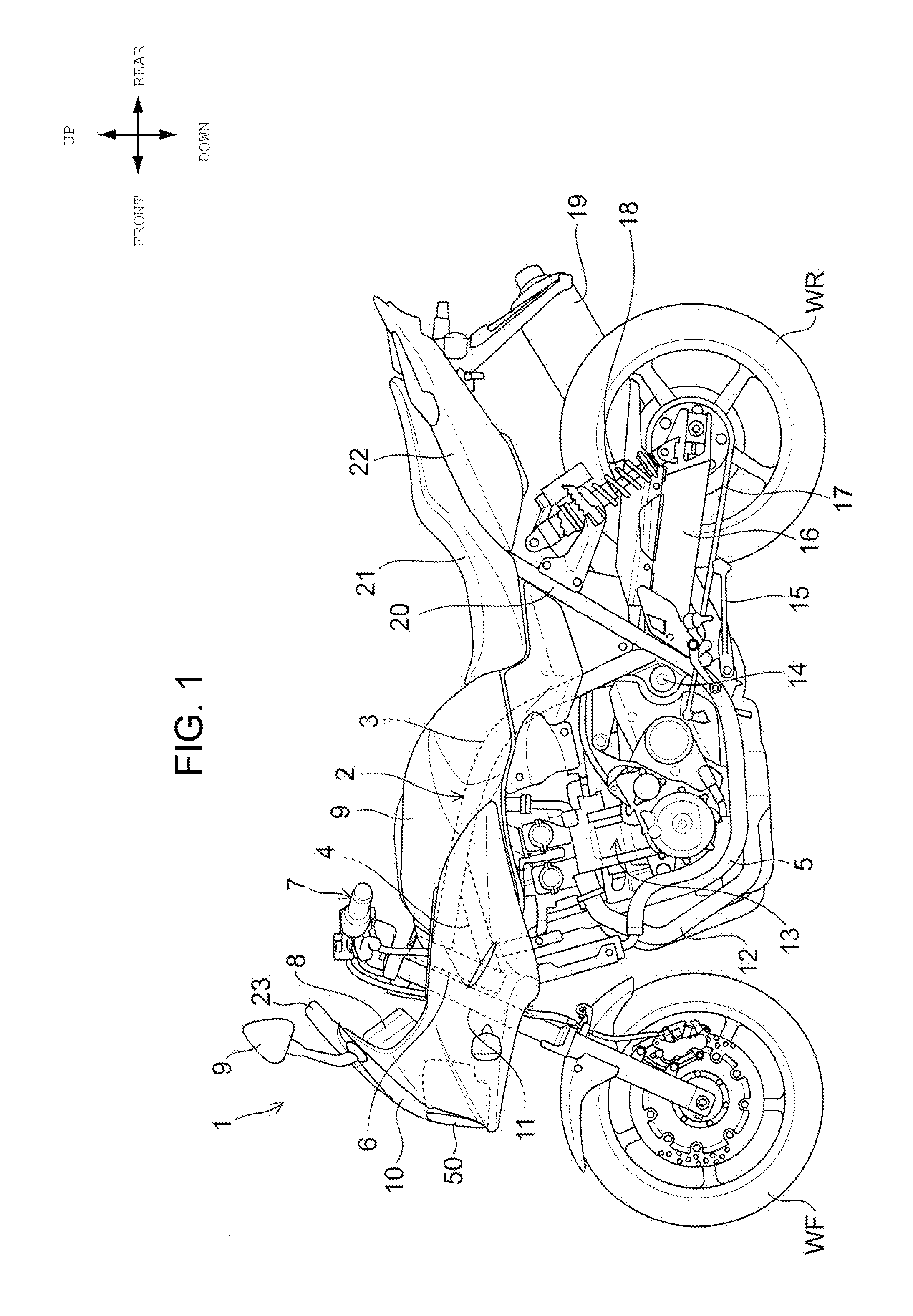
[0037]A preferred embodiment of the present invention is described in detail below with reference to the drawings. FIG. 1 is a left-side view of a motorcycle 1 to which a front lamp (lighting device) 50 according to one embodiment of the present invention is applied. A vehicle-body frame 2 of the motorcycle 1 has left and right main frames 3 extending to a vehicle-body rear side from an upper portion of a head pipe 6, paired under frames 5 extending downward from a reinforcement pipe 4 connecting a lower portion of the head pipe 6 to lower surfaces of the main frames 3, and a seat frame 20 extending from rear portions of the under frames 5 to the vehicle-body rear side and a vehicle-body upper side.

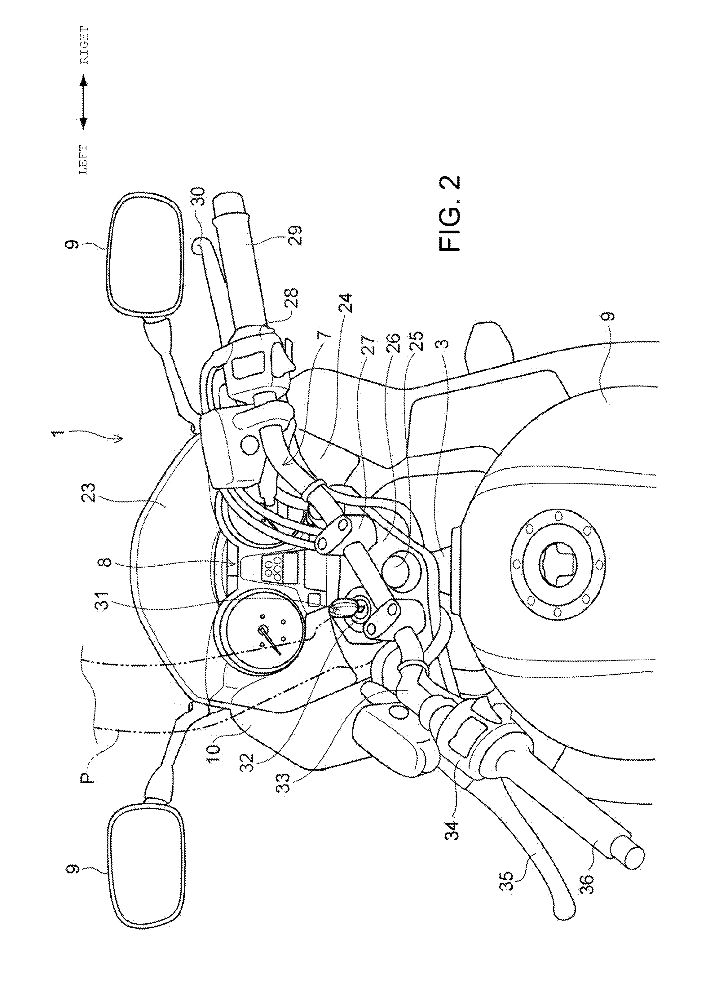
[0038]In front of the head pipe 6, left and right front forks 11 by which a front wheel WF is rotatably supported is supported in such a manner as to be steerable to the left and right, relative to the head pipe 6. A steering handle 7 for steering the front wheel WF is attached to upper e...


PUM


Abstract

A lighting device includes a housing including a front opening portion and a rear opening portion; a light source unit including LED light sources and a heat sink configured to absorb and radiate heat produced by the LED light source; a socket formed by an elastic member and configured to allow the heat sink to be fitted and supported in the rear opening portion such that part of the heat sink is exposed rearward through the rear opening portion and that aiming adjustment is enabled by changing a position of the light source unit relative to the housing. A knob used for manually turning an adjustment screw is attached to a rear end portion of the adjustment screw, and the socket is provided with a rib extending along a circumferential direction of the socket and protruding rearward of the heat sink.

Description

BACKGROUND OF THE INVENTION[0001]1. Field of the Invention[0002]The present invention relates to a lighting device including a light source unit having an LED light source and a heat sink configured to cool the LED light source.[0003]2. Description of Related Art[0004]Conventionally, a lighting device is known, which includes a light source unit integrally having a light source formed by an LED (light-emitting diode) element and a heat sink configured to cool the LED light source. In such a lighting device, an aiming mechanism for adjusting an irradiation direction (optical axis) of the lighting device is generally configured to adjust the angle of placement of the light source unit relative to a housing of the lighting device.[0005]Japanese Patent No. 4582791 discloses a lighting device (front lamp) for vehicle using LED elements as light sources and having the following configuration. The lighting device includes a light source unit having LED elements and a heat sink adjacently p...

Claims


Application Information

Patent Timeline
IPC IPC(8): F21V15/01B62J6/00
CPCF21V15/012B62J6/00F21V15/011B60Q1/0035B60Q1/0683F21S41/192F21S41/395F21S41/55F21S45/50F21S45/48B62J6/026B62J6/025
Inventor TAKENAKA, NOBUYUKIHIRAKIDA, KAZUHIRO
Owner HONDA MOTOR CO LTD
Why Eureka
Eureka Blog
Learn More