
Systems and methods for production of gas wells

a technology of gas wells and production methods, applied in the field of oil and gas wells, can solve the problems of liquid accumulation in the wellbore, decreased pressure and volumetric flow rate of gas, and no longer lifting capacity, so as to reduce the liquid level and reduce the liquid level

Active Publication Date: 2015-01-29
BP CORP NORTH AMERICA INC
View PDF3 Cites 20 Cited by
  • Summary
  • Abstract
  • Description
  • Claims
  • Application Information

AI Technical Summary

Benefits of technology

The patent text describes a method for producing gas from a well by using a production system that includes a casing pipe, a liquid tubing string, and a first production tubing string. The method involves producing gas from a production zone in the subterranean formation through an annulus at a first velocity that is greater than a critical velocity, followed by pumping liquid through the liquid tubing string to reduce the level of liquid in the wellbore. The method also includes shutting in the annulus after the first velocity decreases below the critical velocity, and then producing gas from the production zone through the first production tubing string at a second velocity that is greater than the critical velocity. This method is designed to address various shortcomings associated with previous devices, systems, and methods. The technical effects of this patent include improved gas production and reduced liquid load in the wellbore.

Problems solved by technology

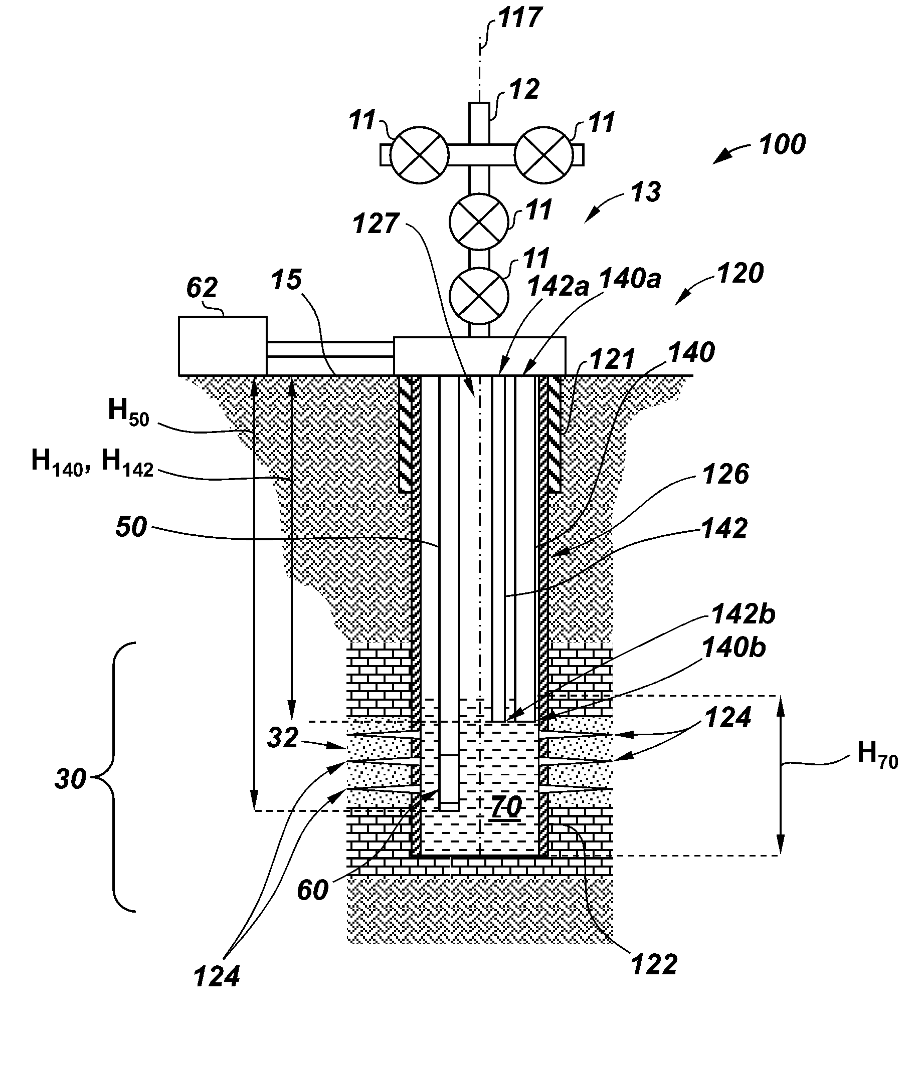
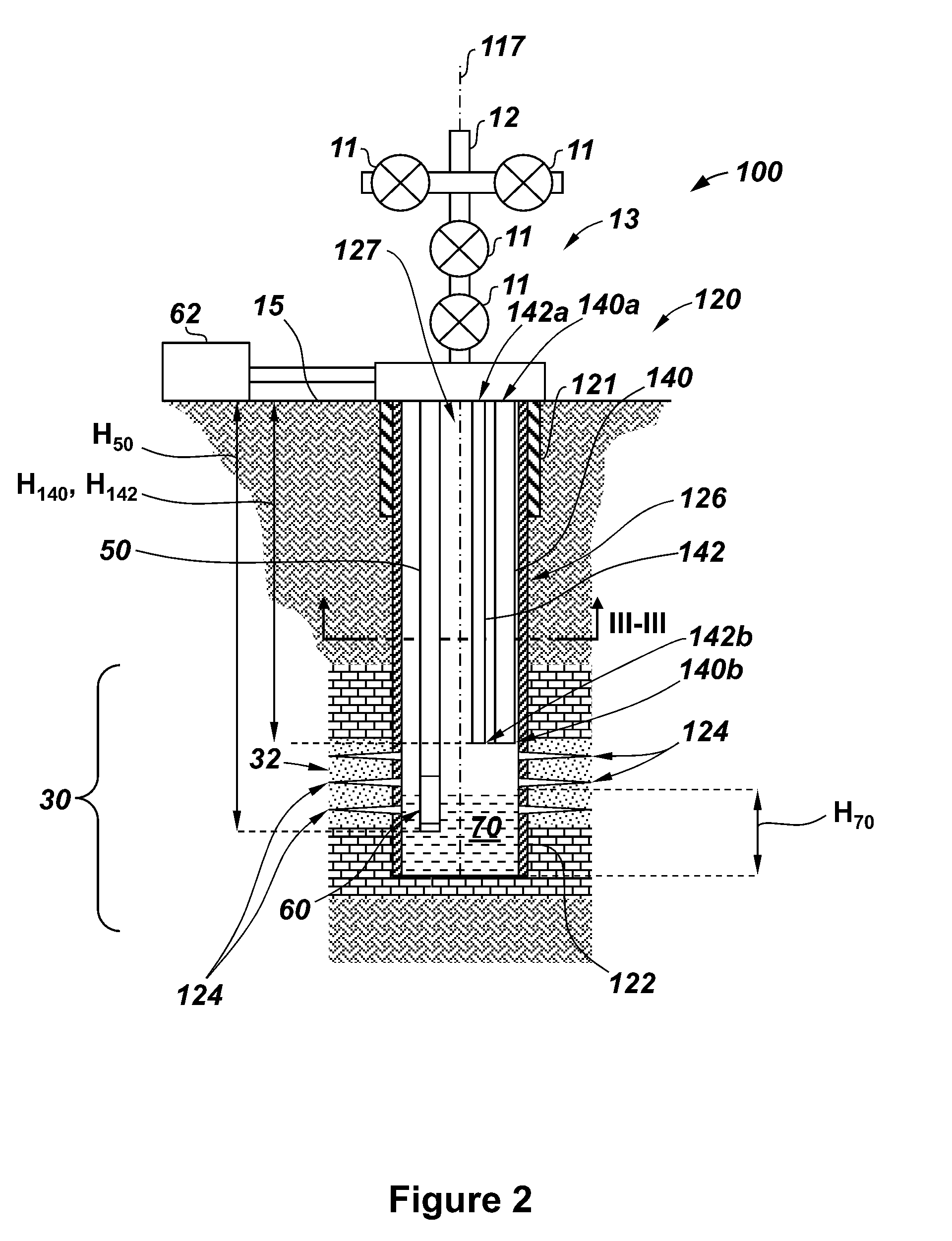
However, in wells where the gas does not provide sufficient transport energy to lift liquids out of the well (i.e., the formation gas pressure and volumetric flow rate are not sufficient to lift liquids to the surface), the liquids accumulate in the wellbore.
However, over time, the pressure and volumetric flow rate of the gas decreases until it is no longer capable of lifting the liquids that enter wellbore 26 to the surface 15.
This column 70 of accumulated liquids imposes a back-pressure on the formation 30 that begins to restrict the flow of gas into wellbore 26, thereby detrimentally affecting the production capacity of the well 20.

Method used


Image

  • Systems and methods for production of gas wells
  • Systems and methods for production of gas wells
  • Systems and methods for production of gas wells

Examples


Embodiment Construction

[0020]The following discussion is directed to various exemplary embodiments. However, one skilled in the art will understand that the examples disclosed herein have broad application, and that the discussion of any embodiment is meant only to be exemplary of that embodiment, and not intended to suggest that the scope of the disclosure, including the claims, is limited to that embodiment.

[0021]Certain terms are used throughout the following description and claims to refer to particular features or components. As one skilled in the art will appreciate, different persons may refer to the same feature or component by different names. This document does not intend to distinguish between components or features that differ in name but not function. The drawing figures are not necessarily to scale. Certain features and components herein may be shown exaggerated in scale or in somewhat schematic form and some details of conventional elements may not be shown in interest of clarity and concis...


PUM


Abstract

A method for producing gas from a well including a wellbore extending from a surface into a subterranean formation, wherein the well also produces liquid, the method including: (a) producing gas from a production zone in the subterranean formation through an annulus extending within the wellbore at a first velocity that is greater than a critical velocity, and (b) pumping liquid through a liquid tubing string after (a) to reduce a level of the liquid within the wellbore. The method also includes: (c) shutting in the annulus after (a) after the first velocity decreases below the critical velocity, wherein the annulus has a first cross-sectional area and the first production string has a second cross-sectional area that is less than the first cross-sectional area, and (d) producing gas from the production zone through the first production tubing string after (c) at a second velocity being greater than the critical velocity.

Description

CROSS-REFERENCE TO RELATED APPLICATIONS[0001]This application claims priority under 35 USC §119(e)(1) of prior U.S. Provisional Patent Application Ser. No. 61 / 859,501, filed Jul. 29, 2013, which is hereby incorporated by reference in its entirety.STATEMENT REGARDING FEDERALLY SPONSORED RESEARCH OR DEVELOPMENT[0002]Not applicable.BACKGROUND[0003]The invention relates generally to oil and gas wells. More particularly, the invention relates to systems and methods for producing hydrocarbon gas from a formation that is also producing liquids.[0004]Geological formations that yield gas also produce liquids that accumulate at the bottom of the wellbore. In general, the liquids comprise hydrocarbon condensate (e.g., relatively light gravity oil) and interstitial water from the reservoir. The liquids accumulate in the wellbore in two ways—as single phase liquids that migrate into the wellbore from the surrounding reservoir, and as condensing liquids that fall back into the wellbore during pro...

Claims


Application Information

Patent Timeline
Patent Type & Authority Applications(United States)
IPC IPC(8): E21B43/14
CPCE21B43/14E21B43/13
Inventor EDWARDS, PAUL A.IDSTEIN, TIMOTHY
Owner BP CORP NORTH AMERICA INC
Learn More