
Large Area Temperature Sensor

Inactive Publication Date: 2015-01-22
PST SENSORS
View PDF11 Cites 19 Cited by
  • Summary
  • Abstract
  • Description
  • Claims
  • Application Information

AI Technical Summary

Benefits of technology

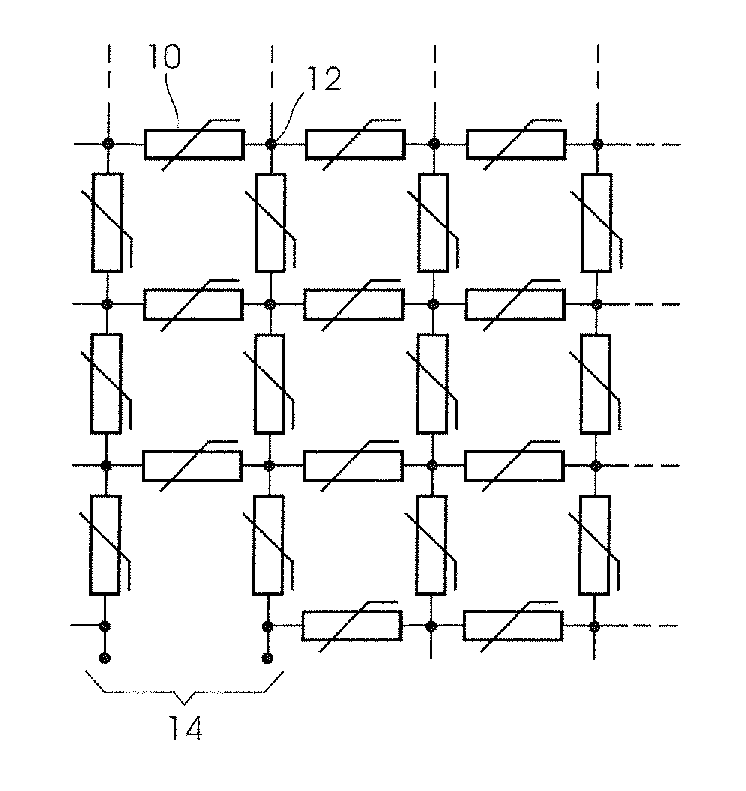
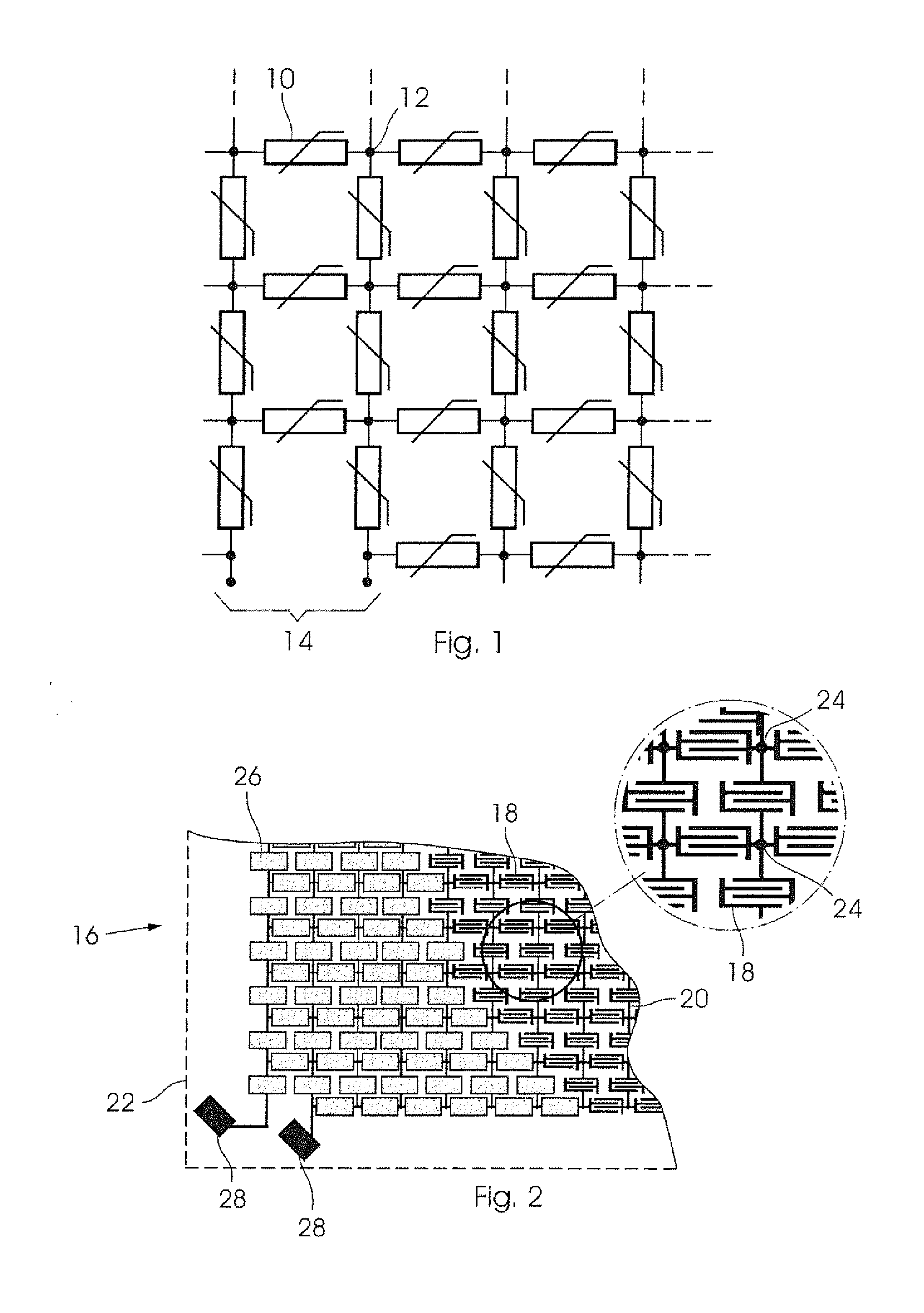
The invention provides a sensing device with a network of identical temperature dependent resistors connected in series and parallel with each other. This network can be reduced in size without changing the resistance value. The resistance between adjacent nodes is constant, and the temperature dependence of the resistance between adjacent nodes is the same as the individual resistors, even if there is a gradient of temperature over the area. The device can comprise a network of electrically conductive contacts and a layer of material with temperature dependent resistance. The substrate can be flexible or rigid, and the conductive contacts and tracks can be formed by screen printing or any other suitable process. The invention allows for precise temperature sensing in a compact and flexible device.

Problems solved by technology

While having the advantage, for some applications, of being a non-contact measurement, this is often a disadvantage due to factors such as extraneous radiation, poor visibility and obscuring of the field of view, transparency of the material and variation in emissivity and reflectivity.

Method used


Image

  • Large Area Temperature Sensor
  • Large Area Temperature Sensor
  • Large Area Temperature Sensor

Examples


Embodiment Construction

[0021]The present invention relates to temperature sensing devices and a method of producing such devices. In particular, the devices may be large area negative temperature coefficient thermistors, produced by printing techniques on thin substrates, which may be cut to size without affecting the characteristics of the device. Of particular relevance here are thermistors which have a negative temperature coefficient of resistance, commonly known as NTC thermistors, meaning that their electrical resistance decreases approximately exponentially with increasing temperature.

[0022]The present invention therefore concerns the use of thermistors, specifically printed negative temperature coefficient (NTC) thermistors, which can be applied as single large area sensor to determine an average temperature or as a temperature sensing array as described in our co-pending provisional patent application Thermal Imaging Sensor, filed on 30 Jan. 2012, where the sensors may be individually addressed o...


PUM

PropertyMeasurementUnit
temperatureaaaaaaaaaa
average resistanceaaaaaaaaaa
resistanceaaaaaaaaaa

Abstract

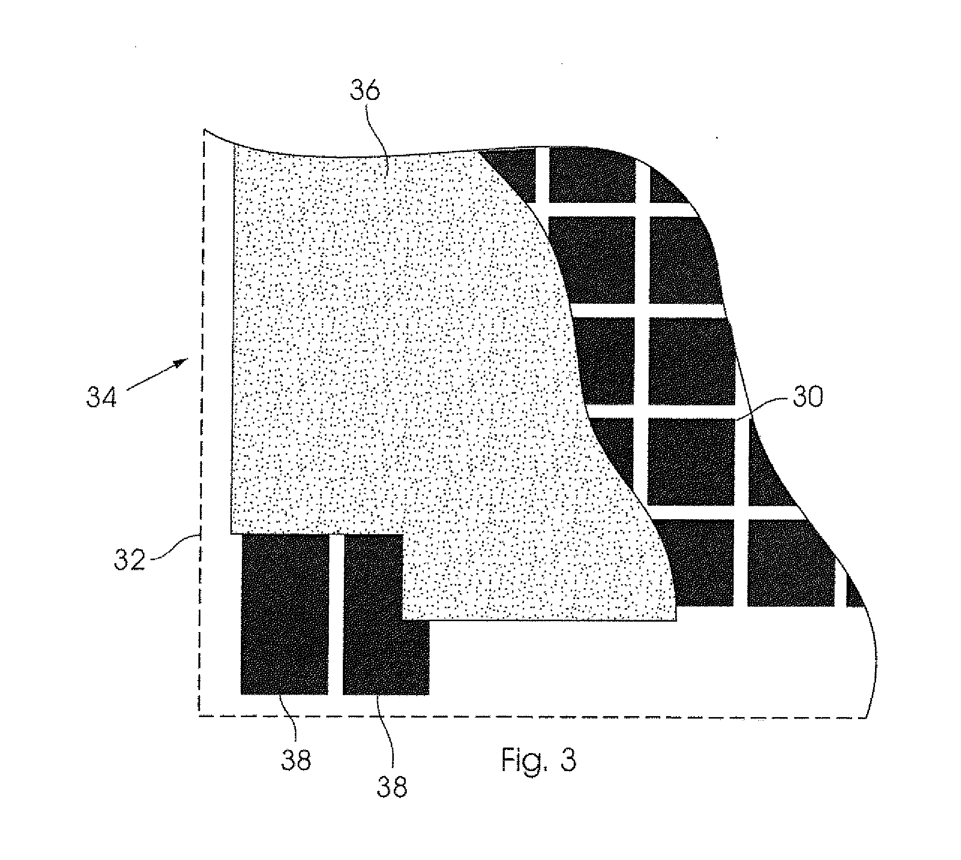
A sensing device is made up of a network of nominally identical temperature dependent resistors which is topologically equivalent to a square resistor network. The device has terminals at which an average resistance value thereof can be measured. The resistors are supported on a substrate which can be reduced in size from an initial size without substantially changing the average resistance value. In preferred embodiments, a pattern of contacts and conductive tracks joining the contacts are printed on a substrate, and a material having a temperature dependent resistance is applied over the contacts to define a network of interconnected thermistors. Alternatively, the material can be applied to the substrate first and the contacts and tracks printed on it.

Description

BACKGROUND OF THE INVENTION[0001]THIS invention relates to temperature sensing devices and a method of producing such devices.[0002]In many applications, in fields as diverse as engineering, health care, packaging and transport, it is desirable to obtain quantitative information on the temperature of a large irregularly shaped object, or of a complex structure whose shape or configuration may change under different conditions or be caused to change. Such an object may be made of thin flexible material such as fabric, polymer film or paper, or may be a rigid or ductile part composed of metal, plastic or a composite material, for example. Alternatively, a sensor may be required to determine the average temperature over a specific portion of a larger area, for example in an environmentally controlled room or chamber, or in a refrigeration unit.[0003]A common method used for such measurements is infrared or visible thermography, in which the radiation emitted by the object is recorded b...

Claims


Application Information

Patent Timeline
Patent Type & Authority Applications(United States)
IPC IPC(8): G01K7/24G01K1/14
CPCG01K1/14G01K7/24H01C7/008H01C13/02H01C7/02H01C1/16H01C7/04G01K2213/00G01K3/06
Inventor BRITTON, DAVID THOMASHARTING, MARGIT
Owner PST SENSORS
Learn More