


Quick Research
Generate reliable direction feasibility study reports for your R&D in just a few steps.

Technical Q&A
Discover and master advanced knowledge NOW. Basics, ideas, possibilities, all at once.

Find Solutions
As an expert in R&D theories, this can generate solutions to your technical problems instantly.

Evaluate Feasibility
Analyze your overall solution with one click, know your potential R&D risks in advance.

Monitor Landscape
Get weekly tech updates, stay abreast of the latest tech innovations and key insights.
Multi-level memory, multi-level memory writing method, and multi-level memory reading method
a multi-level memory and writing method technology, applied in the direction of memory adressing/allocation/relocation, instruments, input/output to record carriers, etc., can solve the problem of energy consumption of writing information on a non-volatile memory, and achieve the effect of reducing consumption energy, increasing the number of times of rewriting, and reducing the number of writing times
- Summary
- Abstract
- Description
- Claims
- Application Information
AI Technical Summary
Benefits of technology
Problems solved by technology
Method used
Image

Examples
first embodiment
2. First Embodiment
[0069]Next, a first embodiment will be described.
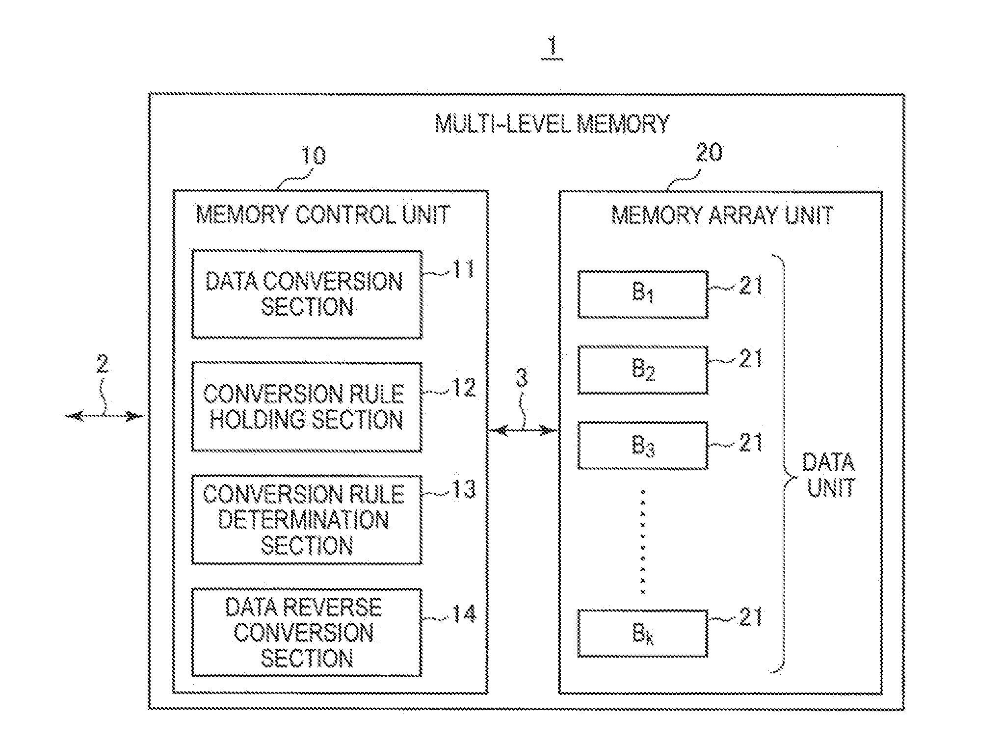
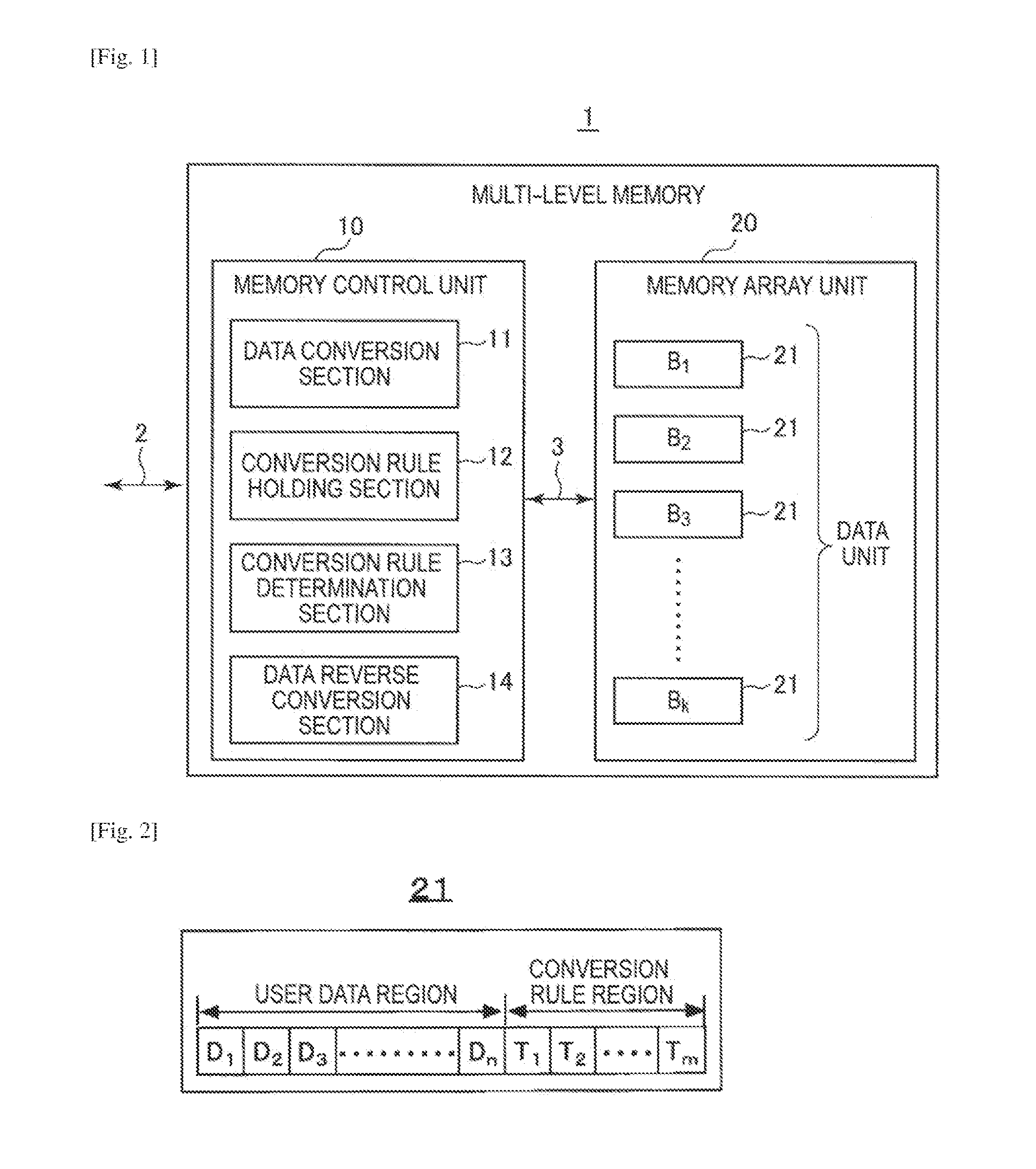
[0070]Herein, a specific conversion rule according to the first embodiment will be present, and an effect obtained by applying the conversion rule will also be described in detail. Note that it is assumed that a memory cell stores two bits and the width of user data is four memory cells in the same manner as in the previous example. In this case, in FIG. 2, the user data region of each data unit 21 includes four memory cells D1, D2, D3, and D4.
[0071]FIG. 7 is a diagram showing conversion rules according to the first embodiment. In the first embodiment, four conversion rules are used. The four conversion rules according to the first embodiment are collectively referred to as a conversion rule set 1. Since the number of conversion rules is four, the number of memory cells necessary for storing a conversion rule identifier is 1. In this case, the conversion rule region of the data unit 21 in FIG. 2 includes one memory ...
second embodiment
3. Second Embodiment
[0082]Next, a second embodiment will be described.
[0083]In the first embodiment, there is a case in which a conversion rule identifier is “11.” Originally, since the goal is to decrease the number of times of writing “11,” even writing “11” in the conversion rule region of the data unit 21 is an operation at odds with the original goal.
[0084]For the purpose of such an operation, the second embodiment changes the conversion rules as shown in FIG. 9. That is, the conversion rule in which the conversion rule identifier is “11” that is originally included in the conversion rule set 1 is omitted. Other conversion rules are the same as the conversion rule set 1.
[0085]The three conversion rules according to the second embodiment are collectively referred to as a conversion rule set 2. Since the number of conversion rules is 3, the number of memory cells necessary for storing the conversion rule identifiers is 1. In this case, as in the first embodiment, the user data re...
third embodiment
4. Third Embodiment
[0092]Next, a third embodiment will be described.
[0093]In the first embodiment, there is a case in which the conversion rule identifier is “11.” On the other hand, in the second embodiment, while there is no case in which the conversion rule identifier is “11,” the number of times of writing “11” in the user data region is greater than that in the first embodiment.
[0094]Thus, in the third embodiment, conversion rules are shown in which there is no case in which the conversion rule identifier is “11,” and at the same time, the number of times of writing “11” in the user data region is equal to that of the first embodiment.
[0095]FIG. 11 is a diagram showing conversion rules according to the third embodiment. The conversion rules themselves are the same as those in the first embodiment.
[0096]The four conversion rules according to the third embodiment are collectively referred to as a conversion rule set 3. Since the number of conversion rules is four, the number of m...
PUM
 Abstract
Description
Claims
Application Information
 - R&D Engineer
- R&D Manager
- IP Professional
- Industry Leading Data Capabilities
- Powerful AI technology
- Patent DNA Extraction
Browse by: Latest US Patents, China's latest patents, Technical Efficacy Thesaurus, Application Domain, Technology Topic, Popular Technical Reports.
© 2024 PatSnap. All rights reserved.Legal|Privacy policy|Modern Slavery Act Transparency Statement|Sitemap|About US| Contact US: help@patsnap.com