Suspension strut for a vehicle

a suspension strut and vehicle technology, applied in the direction of resilient suspensions, vehicle springs, vibration dampers, etc., can solve the problems of disadvantageously not being able to transmit torque, negatively affecting driving comfort of vehicle running gear having a suspension strut of this type, and reducing the mechanical load of individual supporting geometries, and improving the handling of rolling tubes and torsion elements during the mounting of the suspension stru

Active Publication Date: 2015-01-15
THYSSENKRUPP BILSTEIN
View PDF7 Cites 2 Cited by
  • Summary
  • Abstract
  • Description
  • Claims
  • Application Information

AI Technical Summary

Benefits of technology

The present invention provides a suspension strut for a vehicle that improves driving comfort and supports the rolling tube on the damper tube better. The connection between the rolling tube and the damper tube allows torque transmission between them through a torsion element, which compensates for any transverse forces and tilting moments of the rolling tube. The torsion element is accommodated in the radially expanded end of the rolling tube and forms a form-fitting connection with the supporting geometries on the damper tube. Small angular rotations of the rolling tube with respect to the damper tube and the air spring unit can occur without a permanent change occurring in the angle position of the damper tube. The torsion element is made of rubber-elastic material and has a shape-stabilizing body, which improves its fatigue strength and allows for elastic resilience during use of the suspension strut. The damper tube has supporting geometries that improve its rigidity and load capacity. The torsion element is vulcanized or adhesively bonded on the inside of the rolling tube, ensuring a self-retaining arrangement and a correct fit.

Problems solved by technology

An essential disadvantage is that there is no resilience between the rolling tube and the damper tube, so that compensation of transverse forces, in particular of tilting of the damper tube in the rolling tube, is not possible and as a result of which the driving comfort of the vehicle running gear having a suspension strut of this type is negatively affected.
Although a suspension strut that has a rigid arrangement between the damper tube and the rolling tube can allow torque transmission between the damper tube and the rolling tube, the driving comfort is negatively affected by the rigid arrangement.
If, however, a ring part consisting of an elastomer is used to compensate tilting of the rolling tube against the damper tube, it is disadvantageously not possible to transmit torques.

Method used


Image

  • Suspension strut for a vehicle
  • Suspension strut for a vehicle
  • Suspension strut for a vehicle

Examples


Embodiment Construction

[0021]Further features that improve the invention are described in more detail below with the description of a preferred exemplary embodiment of the invention using the figures. In the figures:

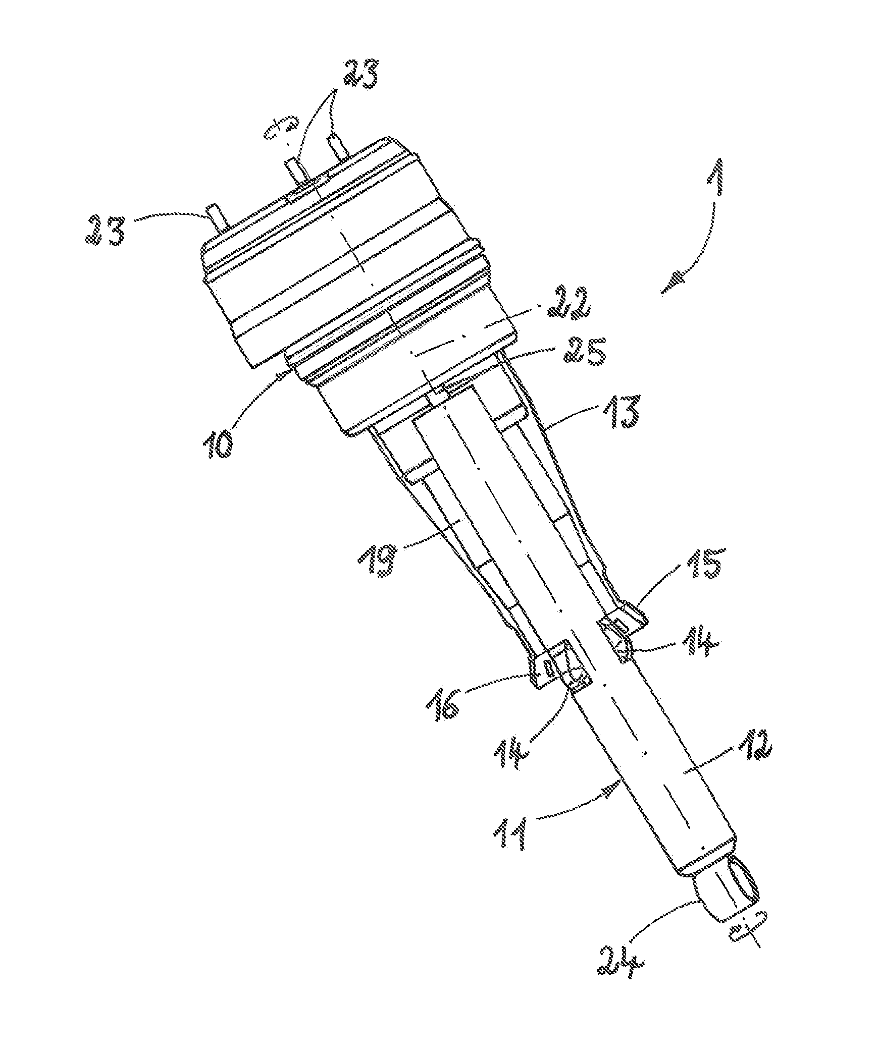
[0022]FIG. 1 shows an exemplary embodiment of a suspension strut in a cut away side view, with an arrangement according to the invention of the rolling tube of an air spring unit on the damper tube of a damper unit;

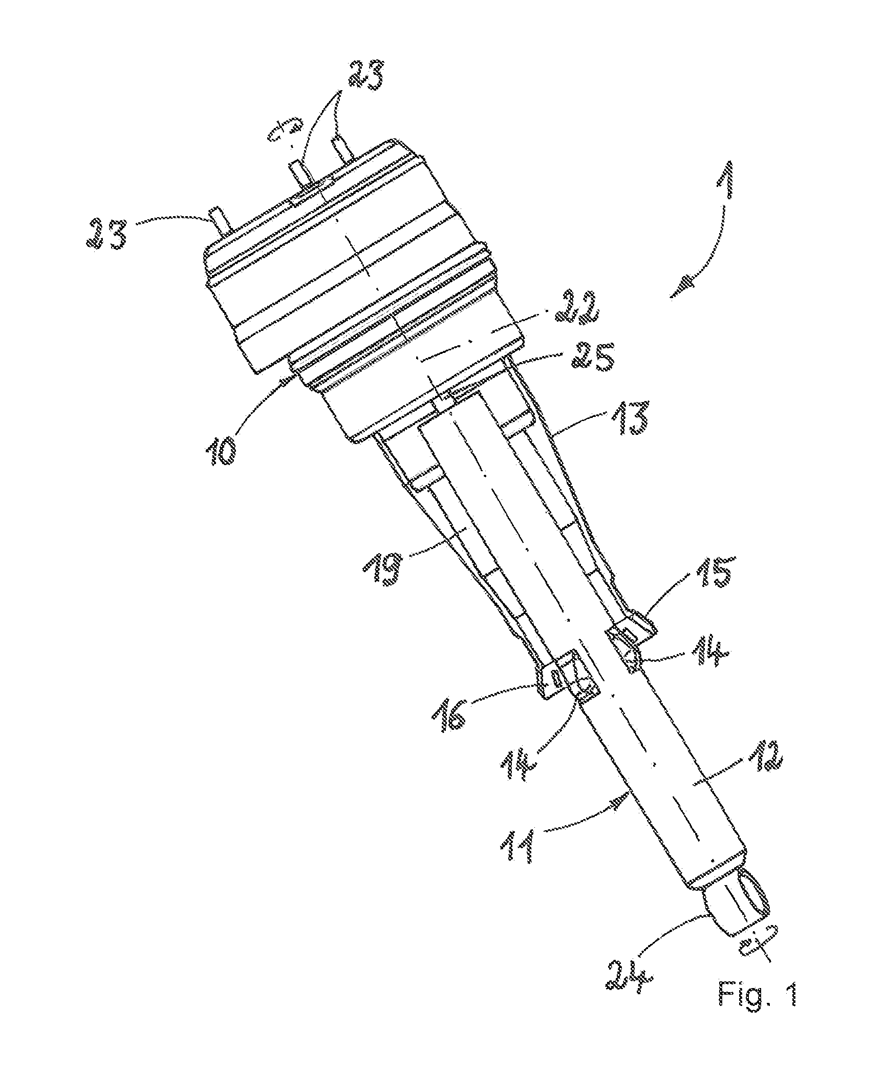
[0023]FIG. 2 shows an enlarged view of a detail of the arrangement of supporting geometries on a damper tube, on which a partially shown torsion element is shown;

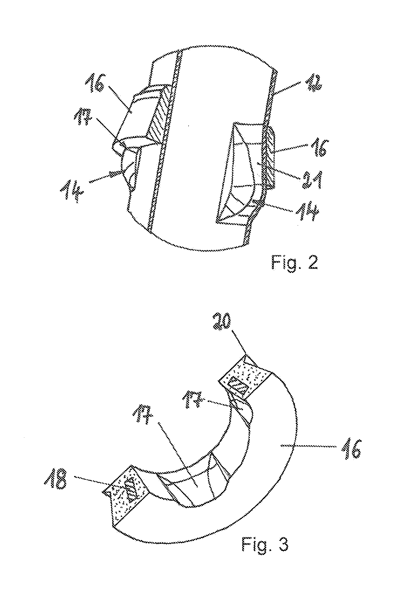
[0024]FIG. 3 shows a perspective view of a torsion element, shown cut away,

[0025]FIG. 4 shows a side view of the arrangement of the torsion element on the damper tube, and

[0026]FIG. 5 shows a cross-sectional view of the damper tube with a torsion element according to the section line A-A as shown in FIG. 4.

[0027]FIG. 1 shows an exemplary embodiment of a suspension strut 1 having the features of the present invention. The su...


PUM


Abstract

A suspension strut for a vehicle has an air spring unit and a damper unit. The damper unit has a damper tube, which extends into a rolling tube of the air spring unit. The damper tube has supporting geometries distributed over its circumference, against which supporting geometries a radially expanded end of the rolling tube is supported. In order to support the rolling tube on the supporting geometries of the damper tube, a torsion element is provided. The torsion element is arranged between the radially expanded end of the rolling tube and the supporting geometries of the damper tube. The torsion element forms a form fit with the supporting geometries for the purpose of torque transmission.

Description

[0001]The present invention relates to a suspension strut for a vehicle having an air spring unit and a damper unit, which damper unit has a damper tube, which extends into a rolling tube of the air spring unit, the damper tube having supporting geometries distributed over its circumference, against which supporting geometries a radially expanded end of the rolling tube is supported.PRIOR ART[0002]DE 102 07 102 B4 discloses a suspension strut for a vehicle having an air spring unit and a damper unit, and the damper unit has a damper tube, which extends into a rolling tube of the air spring unit. To support the rolling tube on the damper tube, the damper tube has supporting geometries, which are configured as stamped portions having a shoulder and against which the end of the rolling tube is supported.[0003]The inner diameter of the rolling tube is configured with an only slightly greater diameter in the region of the support against the damper tube, so that the rolling tube produces...

Claims


Application Information

Patent Timeline
Patent Type & Authority Applications(United States)
IPC IPC(8): B60G15/00B60G15/06B60G11/62B60G15/12
CPCB60G2204/1262B60G15/00B60G2202/14B60G15/12B60G15/06B60G2202/314B60G11/62B60G15/14F16F9/084B60G2204/44B60G2206/40Y02T90/00G06F30/15G06F30/20
Inventor REICHMANN, OLAFWERNER, STEFFENMEINERT, GEORGADAM, MIRCO
Owner THYSSENKRUPP BILSTEIN
Why Eureka
Try Eureka