
Fluid resistance device

a technology of fluid resistance and device, which is applied in the direction of differential pressure volume/mass flow, process and machine control, instruments, etc., can solve the problems of reducing the accuracy of the instrument, affecting the quality of the instrument, so as to achieve the effect of reducing instrumental errors and stably manufacturing

Inactive Publication Date: 2015-01-15
HORIBA STEC CO LTD
View PDF9 Cites 5 Cited by
  • Summary
  • Abstract
  • Description
  • Claims
  • Application Information

AI Technical Summary

Benefits of technology

The present invention allows for the stable manufacturing of a fluid resistance device that prevents fluid from leaking and has consistent resistance characteristics. This reduces instrumental errors and improves the accuracy of the device.

Problems solved by technology

However, when the fixing plates hold the cover plate therebetween, stresses are concentrated at a contact portion between the O-ring and the cover plate and there occurs a slight deflection in the cover plate having a thickness of several tens of microns.
Thus, the resistance characteristics of the fluid resistance device are changed by a slight error of an applied power adjustment when holding the cover plate between the fixing plates.
Therefore, it becomes difficult to stably manufacture the fluid resistance device having uniform resistance characteristics.
In some cases, there may be also a problem that the cover plate is largely deflected and the resistance flow passage would be completely crushed and the fluid would not be able to flow in the resistance flow passage.

Method used


Image

  • Fluid resistance device
  • Fluid resistance device
  • Fluid resistance device

Examples


Embodiment Construction

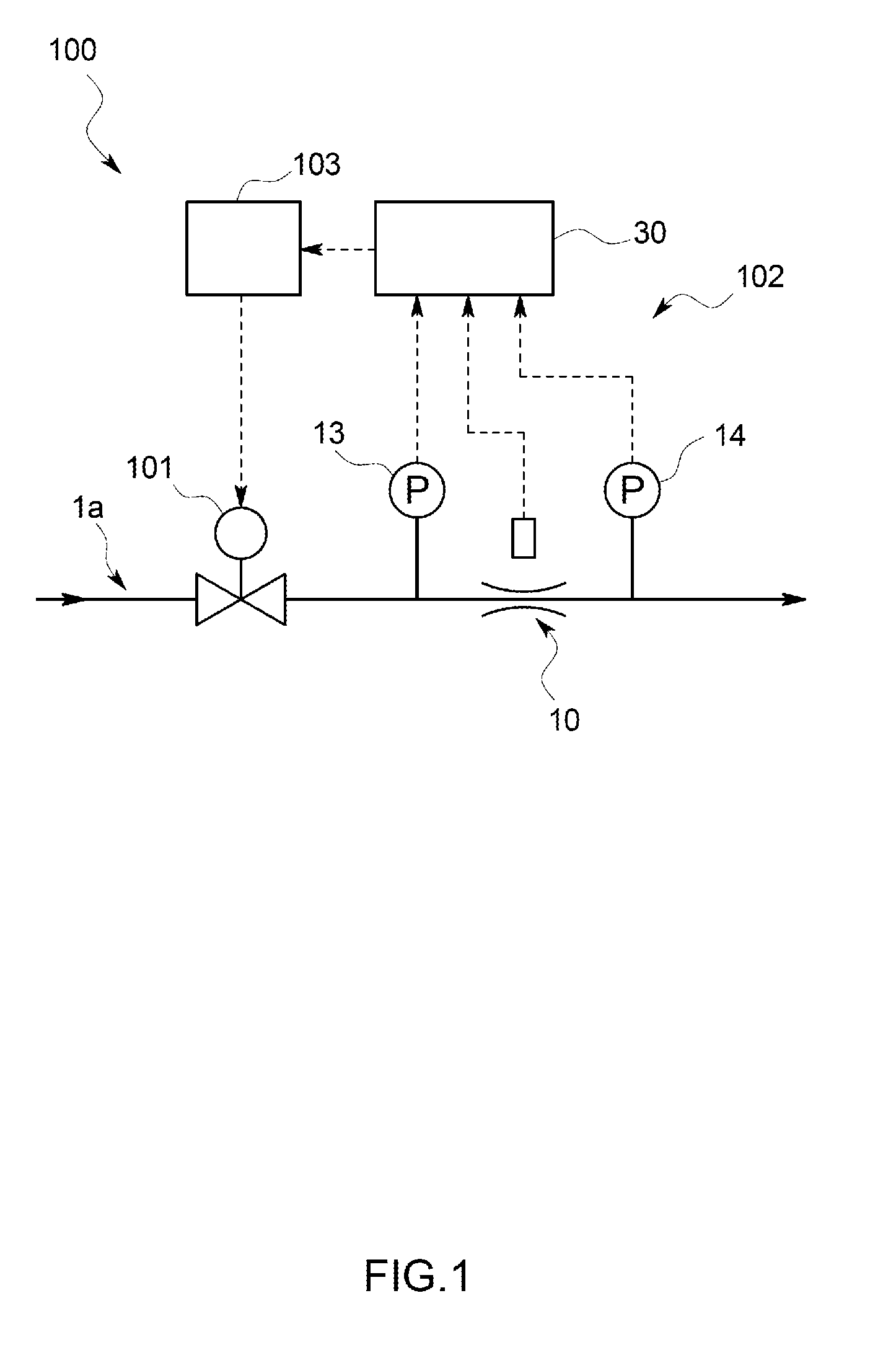
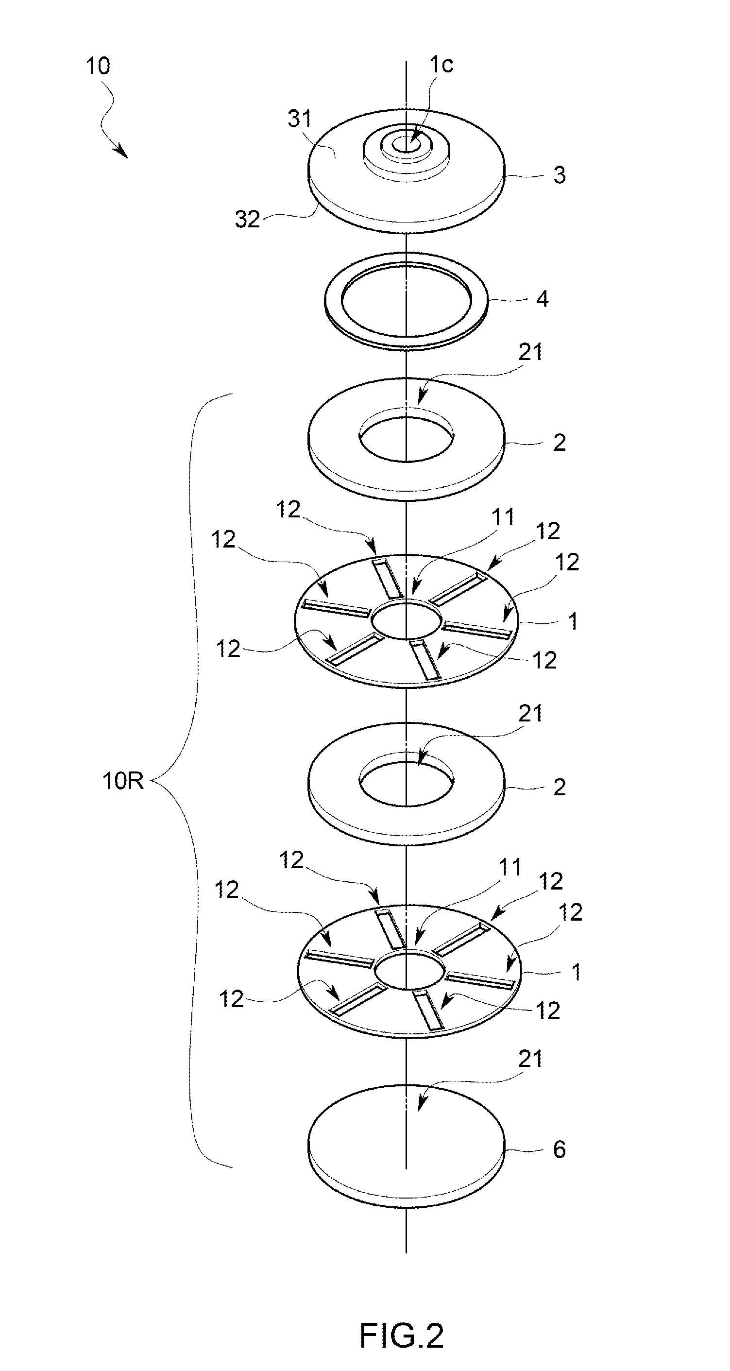
[0023]A fluid resistance device 10 according to the present invention is intended to be used in a flow control device 100.

[0024]The flow control device 100 is used, for example, in a semiconductor manufacturing process and this flow control device 100 is intended to control a mass flow rate when material gas or the like of a semiconductor is directed to flow.

[0025]Specifically, as shown in FIG. 1, this flow control device 100 includes a flow adjusting valve 101 provided on an internal flow passage 1a, a flow rate measuring part 102 provided in a downstream side of the flow adjusting valve 101 and measuring a mass flow rate of fluid flowing in the internal flow passage 1a, and a control circuit 103 for controlling the flow adjusting valve 101 so that the measurement flow rate measured by the flow rate measuring part 102 becomes a predetermined target flow rate.

[0026]The flow rate measuring part 102 is of a differential pressure type and it includes an upstream side pressure sensor 13...


PUM


Abstract

In order to be able to stably manufacture a fluid resistance device having the same resistance characteristics while preventing fluid such as gas from leaking, a fluid resistance device is provided with a fluid resistance element having a resistance flow passage, a base member and a fixing member for holding the fluid resistance element to be fixed between the base member and the fixing member, and a thin plate-shaped seal member interposed between the fixing member and the fluid resistance element.

Description

TECHNICAL FIELD[0001]The present invention relates to a fluid resistance device for use in, for example, a flow control device for controlling a flow rate of fluid or a flow rate measuring device for measuring a flow rate of fluid.BACKGROUND ART[0002]A fluid resistance device implies a device having a flow passage (also referred to as “resistance flow passage” hereinafter) acting as a resistance when fluid flows therein and a flow rate of the fluid can be measured based on pressures in an upstream side and a downstream side thereof when the fluid is directed to flow through this fluid resistance device.[0003]For example, in the case of a flow control device for controlling a flow rate of material gas used for manufacturing a semiconductor, the fluid resistance device for use therein is required to have a very fine accuracy in controlling the flow rate, and a resistance flow passage is required to have a thickness of several tens of microns in some cases.[0004]Therefore, for example,...

Claims


Application Information

Patent Timeline
IPC IPC(8): F16L55/027
CPCF16L55/02718G01F1/40G05D7/0635Y10T137/85938
Inventor YASUDA, TADAHIRO
Owner HORIBA STEC CO LTD
Learn More