
On The Dynamic Response of Actuation Devices in Nonlinear Dynamics Systems

a nonlinear dynamics and dynamic response technology, applied in the field of actuation devices, can solve the problems of reducing the effectiveness of the control system, the system operation must be relatively slow, and the dynamic response issue has not been fully explained for the nonlinear dynamics system, and achieves the effect of speed and precision

Active Publication Date: 2015-01-08
OMNITEK PARTNERS LLC
View PDF1 Cites 3 Cited by
  • Summary
  • Abstract
  • Description
  • Claims
  • Application Information

AI Technical Summary

Benefits of technology

This patent presents a new way to study the response requirements of mechanical systems with open-loop kinematic chains and nonlinear dynamics, such as robot manipulators. The system actuators have two groups of components: one is independent of the actuator motion and has limitations dictated by the driving power amplifiers, electronics, computational, and signal processing devices and components. The other group is dependent on the actuator motion and has limitations dictated mainly by the effective inertia of the actuator and its operating speed. This new approach is needed for achieving higher performance in terms of speed and precision in mechanical systems, such as robot manipulators.

Problems solved by technology

However, dynamic response issues have not been fully explained for nonlinear dynamics systems, including mechanical systems such as robot manipulators.
For highly nonlinear dynamics systems, this usually means that the system operation must be relatively slow to ensure stability and effectiveness of the control system in providing operational precision.
The lack of full understanding of the dynamic response characteristics and limitations of the actuation systems of mechanical systems with highly nonlinear dynamics, however, significantly reduces the effectiveness of their control system.
The dynamic response of this group of components of the actuating forces / torques is shown to be limited only by the dynamic response limitations—for the case of electrically driven actuation systems—of the driving power amplifiers, electronics, computational and signal processing devices and components.
The dynamic response of this group of components of the actuator forces / torques is limited mainly by the effective inertia that is experienced by the actuator and its operating speed.

Method used


Image

  • On The Dynamic Response of Actuation Devices in Nonlinear Dynamics Systems
  • On The Dynamic Response of Actuation Devices in Nonlinear Dynamics Systems
  • On The Dynamic Response of Actuation Devices in Nonlinear Dynamics Systems

Examples


example and

Simulation

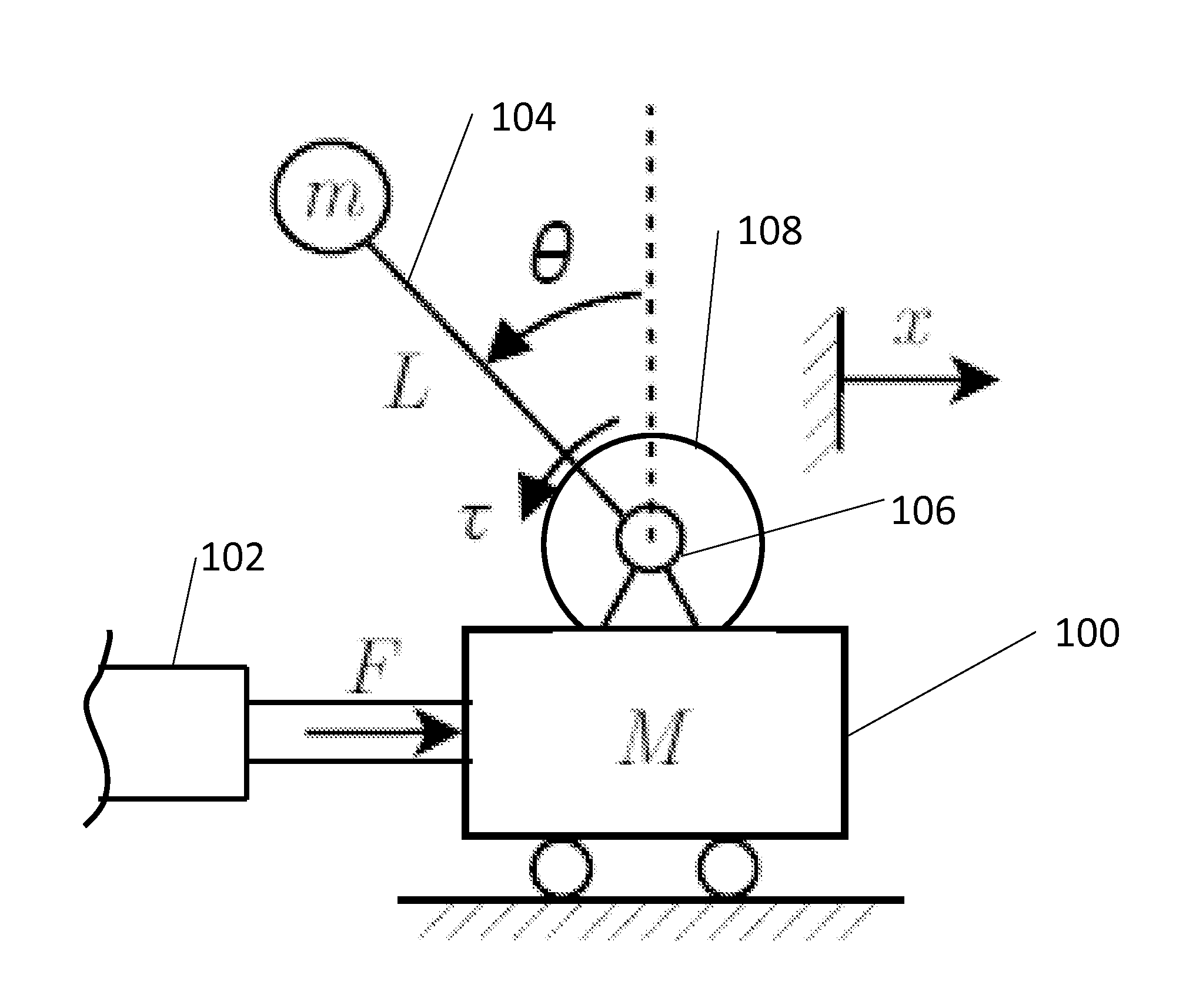
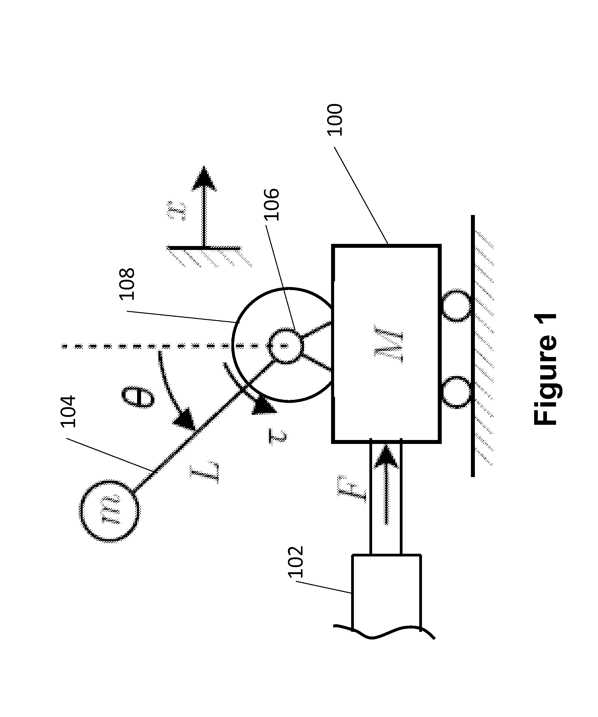
[0032]Consider the inverse pendulum system of FIG. 1. The conventional approach for constructing a model-based feed-forward control with a linear feedback loop is shown in the block diagram of FIG. 3. In this control system, the input desired motion xd and θd and their related velocities and accelerations are used in the system equations of motion Eqn. (6) and Eqn. (7) to calculate the feed-forward force Fff and torque τff, respectively. In the block diagram of FIG. 3, the actual position of the cart 100 and the pendulum link 104 are indicated as xa and θa, respectively. Their corresponding error signals, i.e., the difference between the desired and actual positions ex and eθ and related velocities are fed back through a (usually a linear PD) controller 200. The sum of the feed-forward and the feedback signals is then sent to the electronic power amplifier 204 via a low pass filter 202, which is used to remove the high frequency components of the signal that are considered...


PUM


Abstract

A method for actuating a motor including: separating feed-forward signals corresponding to motion independent components of a required actuating force / torque from motion dependent components; filtering the motion dependent components of the feed-forward signals to at least reduce high frequency signals generated due to feedback signals; and either not filtering or filtering with a low pass filter having a higher cut off frequency the motion independent components of the feed-forward signals to at least reduce higher frequency noise and components; wherein higher frequency components of electronic power amplifier signals corresponding to the motion independent components of the actuating forces / torques are not eliminated by the low pass filter, thereby ensuring that the reaction forces / torques are provided to actuate the motor.

Description

CROSS-REFERENCE TO RELATED APPLICATION[0001]This application claims the benefit to U.S. Provisional Application No. 61 / 833,391 filed on Jun. 10, 2013, the entire contents of which is incorporated herein by reference.BACKGROUND[0002]1. Field of the Invention[0003]The present invention relates generally to actuation devices, and more specifically to the dynamic response of actuation devices in nonlinear dynamics systems.[0004]2. Prior Art[0005]The dynamics of actuation devices of different types have been extensively studied. A comprehensive review of studies related to different types of electrical motors is known in the art. Furthermore, different methods have been studied for synthesizing trajectory and control mechanical systems with nonlinear dynamics such as robot manipulators. For example, formulation of inverse dynamics and model-based feed-forward control of dynamics systems such as robot manipulator have been studied and trajectory synthesis for minimal actuation force / torqu...

Claims


Application Information

Patent Timeline
Patent Type & Authority Applications(United States)
IPC IPC(8): H02P6/08
CPCH02P6/08B25J9/1628H02P2207/05G05B19/19G05B2219/40077G05B2219/41144G05B2219/41426G05B2219/42153G05B2219/41129H02P29/00
Inventor RASTEGAR, JAHANGIR S.FENG, DAKE
Owner OMNITEK PARTNERS LLC
Learn More