
Conveyance control apparatus

a control apparatus and conveying technology, applied in the field of conveying control apparatuses, can solve the problems of large influence of air resistance or the like on the freely falling paper sheets, low falling speed of paper sheets, and difficulty in accurately judging the full stack state.

Active Publication Date: 2015-01-01
RISO KAGAKU CORP
View PDF1 Cites 9 Cited by
  • Summary
  • Abstract
  • Description
  • Claims
  • Application Information

AI Technical Summary

Benefits of technology

The invention aims to accurately determine the number of paper sheets stacked on a base without being affected by air resistance or misalignment. It achieves this by stopping the feeding of paper sheets when the sensor's on time is equal to or greater than the time required for the paper sheet to reach the full-stack state.

Problems solved by technology

However, when the stacked volume on the paper sheet eject tray becomes large, the influence of air resistance or the like on the freely falling paper sheets becomes large.
As a result, when the stacking amount is large, the falling speed of the paper sheet is low.
However, because the residual capacity is merely estimated by calculating a pulse width for each type of paper sheet (a size, weight, shape, or the like, of the paper sheet), the paper sheets are stacked without considering the influence of a stacking misalignment, or the like.
Therefore, it is difficult to accurately judge the full-stack state.
In particular, when the falling speed of the paper sheet is remarkably low, ejected paper sheets come into contact with each other, which is likely to result in stacking misalignment.

Method used


Image

  • Conveyance control  apparatus
  • Conveyance control  apparatus
  • Conveyance control  apparatus

Examples


Embodiment Construction

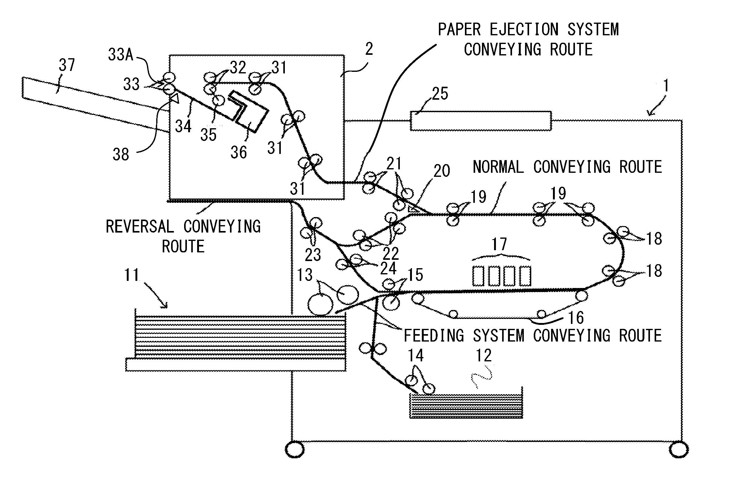
[0019]Embodiments of the present invention are described below with reference to the drawings. FIG. 1 illustrates an internal configuration of an ink-jet printer (hereinafter simply referred to as a “printer”) 1 as an example of a printing device. To the printing device, an arbitrary printing device other than the ink-jet printer can be applied. The printing device may be, for example, a stencil printing machine or a laser printer.

[0020]In addition, FIG. 1 illustrates a configuration in which a paper sheet ejector device 2 is connected as an optional device to the printer 1, but rather than the paper sheet ejector device 2, a mere paper sheet eject tray may be provided to the printer 1.

[0021]The printer 1 is a device that prints a prescribed image, character, illustration, or the like on a paper sheet. The paper sheet ejector device 2 is a device that performs prescribed post-processing on the paper sheet on which the printer 1 has performed printing, and ejected the paper sheet. Th...


PUM

PropertyMeasurementUnit
Timeaaaaaaaaaa

Abstract

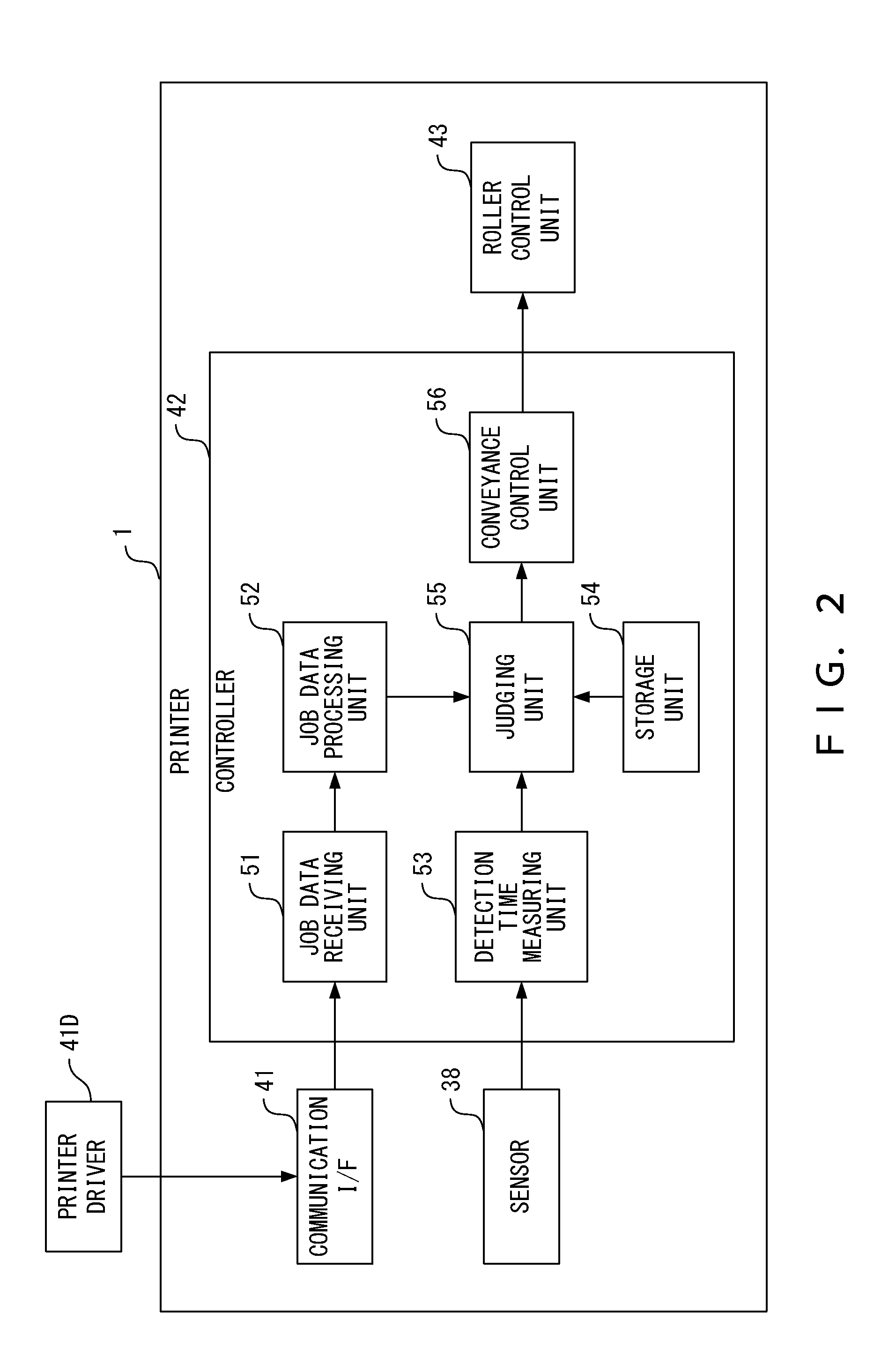
A conveyance control apparatus includes a stacking base that stacks ejected paper sheets, a sensor that detects a paper sheet after the paper sheet is ejected according to job data before the paper sheet is stacked on the stacking base, a detection time measuring unit that measures sensor-on time during which the sensor detects the paper sheet, a storage unit that stores near-full-stack time for judging whether stacked volume on the stacking base enters into a near-full-stack state, a judging unit that judges stack state on the stacking base based on paper sheet information of the job data and a measured result by the detection time measuring unit, and a conveyance control unit that performs control to temporarily stop paper sheet feeding and then to feed predetermined number of paper sheets, when the judging unit judges that the sensor-on time is equal to or greater than the near-full-stack time.

Description

CROSS-REFERENCE TO RELATED APPLICATIONS[0001]This application is based upon and claims the benefit of priority of the prior Japanese Patent Application No. 2013-137232, filed on Jun. 28, 2013, the entire contents of which are incorporated herein by reference.TECHNICAL FIELD[0002]The present invention is related to a conveyance control apparatus applied to a printing device, such as a printer.BACKGROUND ARTS[0003]An ink-jet printer is an example of a printing device. Paper sheets after being printed by an ink-jet printer are ejected onto a paper sheet eject tray. When the paper sheets are in almost a full stack on the paper sheet eject tray, this state is detected as a near-full-stack state (near-full), and a user is warned of this state. When paper sheets are further ejected after being stacked up to the near-full state, the paper sheet eject tray will enter into the full-stack state. When the paper sheet stack tray is in the full-stack state, printing is interrupted. Then, a warnin...

Claims


Application Information

Patent Timeline
IPC IPC(8): B65H43/00B65H31/00
CPCB65H31/00B65H43/00B65H43/06B65H31/02B65H2301/4212B65H2511/30B65H2513/50B65H2513/512B65H2601/421B65H2801/06
Inventor OGAWA, HIDEAKIHANAMOTO, YOSHIHIROHARA, YOSHIKAZUMORI, KAZUAKITAKANOHASHI, HIROAKIMINOWA, YOUSUKEKONO, YOSHIAKI
Owner RISO KAGAKU CORP
Learn More