Pulse injection apparatus

a pulse injection and apparatus technology, applied in the direction of single pulse train generator, coupling device connection, instruments, etc., can solve the problems of high cost, inability to use pulses with a peak voltage of several tens of kv or more, complicated test environment configuration,

Active Publication Date: 2015-01-01
ELECTRONICS & TELECOMM RES INST
View PDF6 Cites 11 Cited by
  • Summary
  • Abstract
  • Description
  • Claims
  • Application Information

AI Technical Summary

Benefits of technology

The present invention is a coupling clamp-type pulse injection apparatus that can connect a high-voltage pulse with a peak voltage of several tens of kV and a rising time of several hundreds of ps or less to a cable without causing dielectric breakdown and a 50Ω impedance mismatch. The technical effect of the invention is to enable the safe and effective coupling of high-voltage pulses to cables.

Problems solved by technology

However, the radiative test is characterized in that the configuration of a test environment is complicated and thus cost is high, and in that the influence of a distance and a surrounding environment is large, and thus a pulse having intensity lower than the output of pulse generation equipment is coupled to the cable.
However, since the device is implemented using N-type I / O connectors having an insulation withstanding voltage, it cannot be used at a pulse having a peak voltage of several tens of kV or more.
Further, since the device is implemented to be capable of injecting a pulse having a rising time of 5 ns, it may be difficult to use the device due to the problem of a parasitic component and impedance mismatch when a wideband pulse having a rising time of several hundreds of ps or less is injected.
Therefore, it is difficult to use the coupling clamp injection device presented in the exiting paper or existing standards as a test device for injecting a high-voltage wideband pulse having a peak voltage of several tens of kV and having a rising time of several hundreds of ps or less.
When calculation is made using the following Equation (1), frequencies of up to GHz must be usable so as to inject a pulse having a rising time of several hundreds of ps or less, but the injection device presented in U.S. Pat. No. 5,477,153 is disadvantageous in that only frequencies of up to 100 MHz can be used, and the magnitude of an injectable peak voltage is small, thus making it difficult to use the device as a device for injecting a high-voltage wideband pulse having a peak voltage of several tens of kV or more and having a rising time of several hundreds of ps.
This device has a sufficient injection voltage, but it is impossible to use the device to inject a wideband pulse having a rising time of several hundreds of ps.

Method used


Image

  • Pulse injection apparatus
  • Pulse injection apparatus
  • Pulse injection apparatus

Examples


Embodiment Construction

[0041]Hereinafter, a pulse injection apparatus according to embodiments of the present invention will be described in detail with reference to the attached drawings. Prior to the detailed description of the present invention, it should be noted that the terms or words used in the present specification and the accompanying claims should not be limitedly interpreted as having their common meanings or those found in dictionaries. Therefore, the embodiments described in the present specification and constructions shown in the drawings are only the most preferable embodiments of the present invention, and are not representative of the entire technical spirit of the present invention. Accordingly, it should be understood that various equivalents and modifications capable of replacing the embodiments and constructions of the present invention might be present at the time at which the present invention was filed.

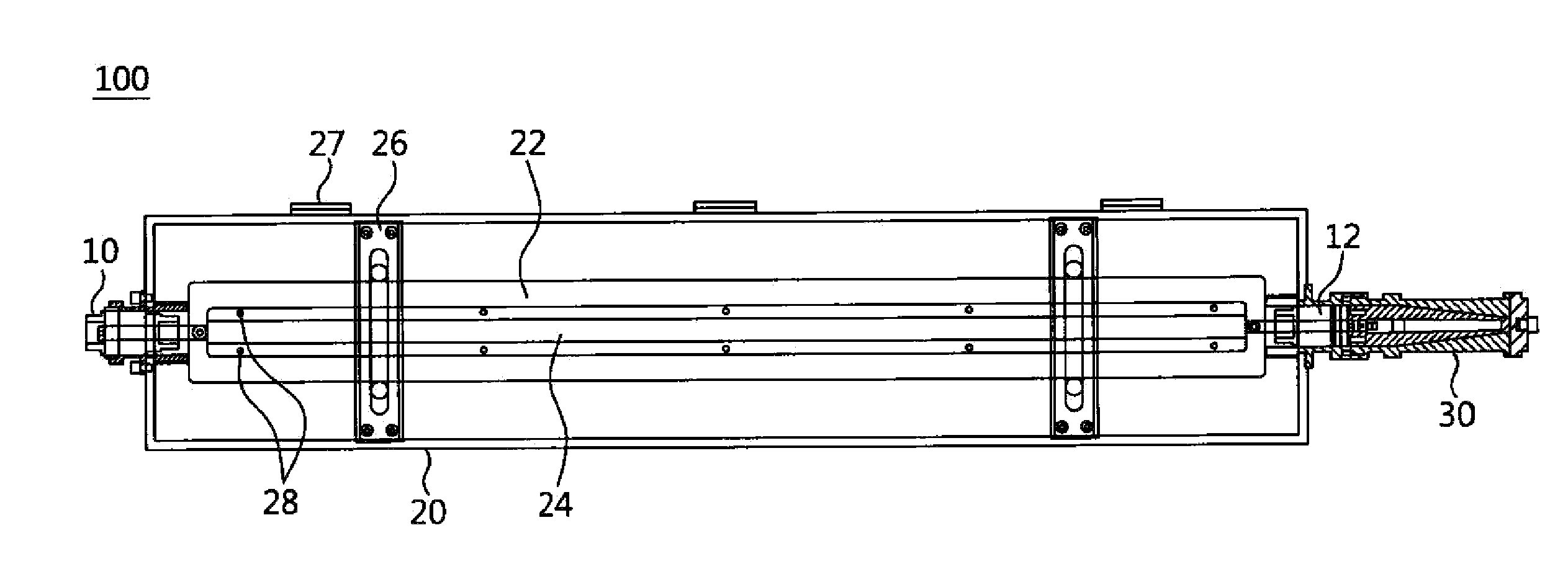
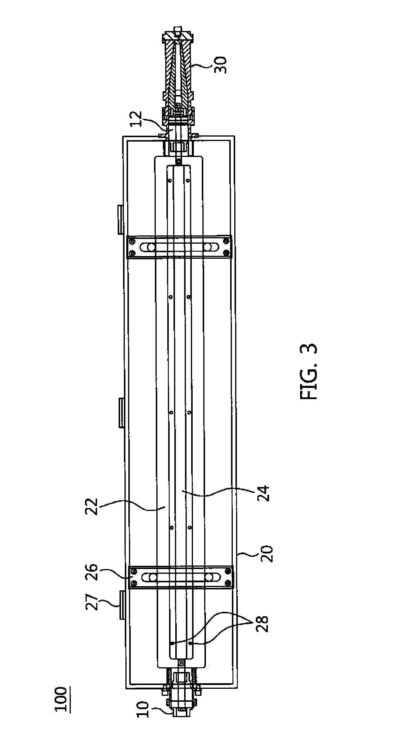
[0042]FIG. 3 is a diagram showing a pulse injection apparatus according to an e...


PUM


Abstract

A coupling clamp-type pulse injection apparatus, which can couple a high-voltage wideband pulse having a peak voltage of several tens of kV and having a rising time of several hundreds of ps or less to a cable without causing dielectric breakdown and a 50 ohm impedance mismatch, is provided. The pulse injection apparatus includes an input connector, an output connector, and a main body including an inner plate connected at a first end thereof to the input connector and at a second end thereof to the output connector, and a coupling plate connected to the inner plate and configured to fix a cable to the inner plate and to couple a high-power electromagnetic pulse input through the input connector to the cable.

Description

CROSS REFERENCE TO RELATED APPLICATION[0001]This application claims the benefit of Korean Patent Application No. 10-2013-0074673 filed on Jun. 27, 2013, which is hereby incorporated by reference in its entirety into this application.BACKGROUND OF THE INVENTION[0002]1. Technical Field[0003]The present invention relates generally to a pulse injection apparatus and, more particularly, to a coupling clamp-type pulse injection apparatus, which is used for a test in the analysis of the effects of a conductive high-power electromagnetic pulse (EMP).[0004]2. Description of the Related Art[0005]High-power electromagnetic pulses may be divided into nuclear electromagnetic pulses and non-nuclear electromagnetic pulses. A nuclear electromagnetic pulse typically denotes a high altitude electromagnetic pulse (HEMP) caused by nuclear explosion occurring at an altitude of 30 km or more. A non-nuclear electromagnetic pulse denotes intentional high-power electromagnetics (HPEM) caused by instantaneou...

Claims


Application Information

Patent Timeline
IPC IPC(8): H01R31/06
CPCH01R31/065G01R31/001G01R31/021G01R31/58G01R29/08H03K3/78H01R24/42H01R24/542
Inventor NAMKOONG, UPRYU, SEUNG-KABKIM, UIJUNGCHU, KWANG-UK
Owner ELECTRONICS & TELECOMM RES INST
Why Eureka
Try Eureka