
Wireless power transmission apparatus using ultrasound

a power transmission apparatus and ultrasound technology, applied in direction finders using ultrasonic/sonic/infrasonic waves, instruments, sustainable buildings, etc., can solve the problems of limited use of power transmission apparatuses using electromagnetic induction, low energy densities, and small energy amounts after energy conversion, so as to increase the efficiency of wireless power transmission

Active Publication Date: 2015-01-01
ELECTRONICS & TELECOMM RES INST
View PDF4 Cites 239 Cited by
  • Summary
  • Abstract
  • Description
  • Claims
  • Application Information

AI Technical Summary

Benefits of technology

The patent describes a wireless power transmission device that uses ultrasound to optimize the distance between the transmitter and receiver, which improves the efficiency of wireless power transmission. This means that more efficient and effective wireless power can be transmitted using this technology.

Problems solved by technology

Accordingly, power transmission apparatuses using electromagnetic induction are limited to being used when a distance between the charge parent and the power receiving module is short such as several centimeters.
However, since RFs have low energy densities, energy amounts after energy conversion are small.
However, as in the case of under water or human skin, when an ultrasound transmitter and an ultrasound receiver are separated from each other, efficiency of power transmission between the ultrasound transmitter and ultrasound receiver decreases.

Method used


Image

  • Wireless power transmission apparatus using ultrasound
  • Wireless power transmission apparatus using ultrasound
  • Wireless power transmission apparatus using ultrasound

Examples


Embodiment Construction

[0018]Hereinafter, in order to allow a person with ordinary skill in the art to easily execute technical thoughts of the present invention, embodiments of the present invention will be described in detail with reference to the attached drawings. Like reference numerals refer to like elements. Similar reference numerals refer to similar elements. The embodiments to be described below are just examples and may be variously changed and modified within a range of the technical thoughts of the present invention.

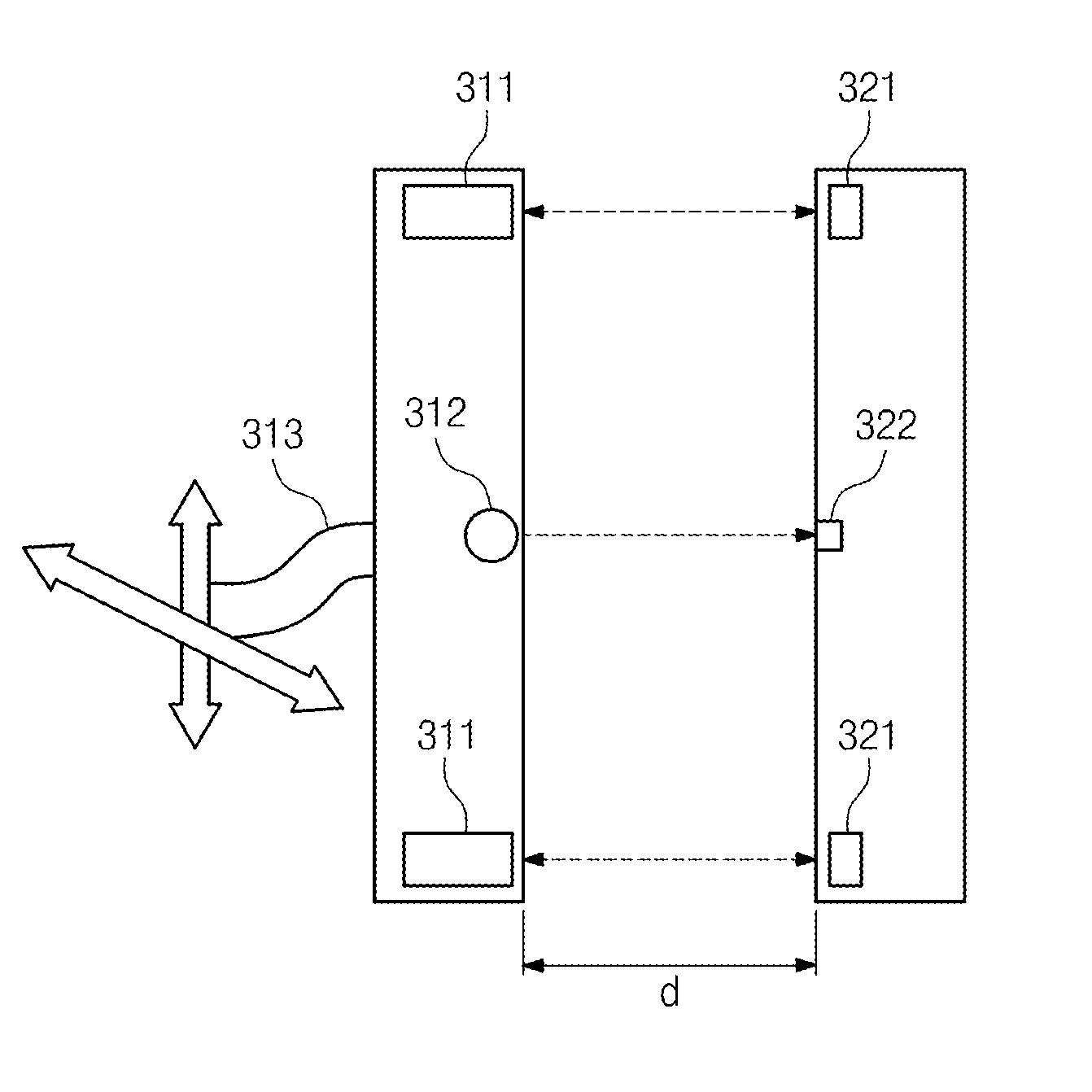
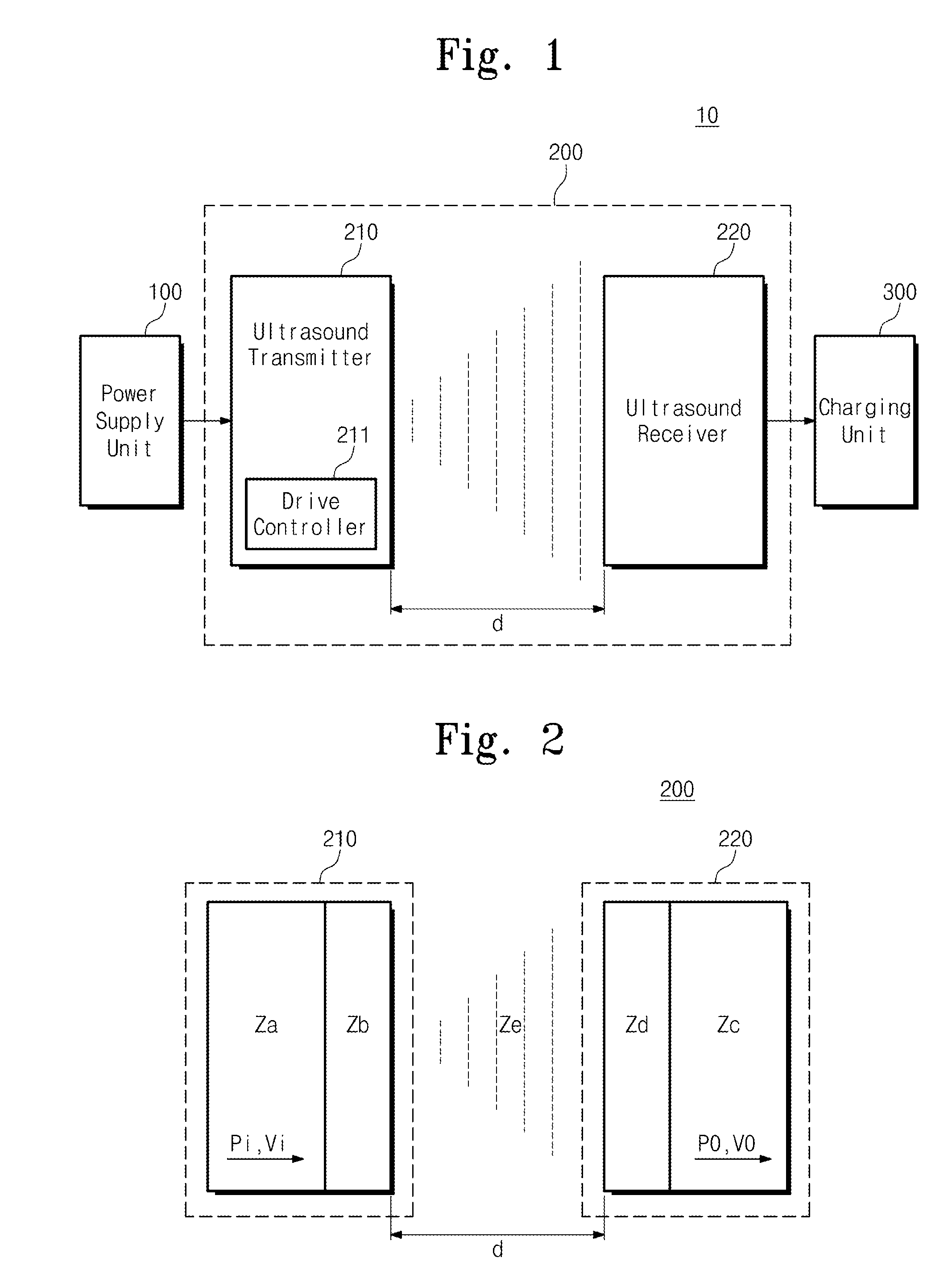
[0019]FIG. 1 is a block view illustrating a wireless power transmission apparatus 10 according to an embodiment of the present invention. Referring to FIG. 1, the apparatus 10 includes a power supply unit 100, an ultrasound transmission unit 200, and a charging unit 300.

[0020]The power supply unit 100, in response to an external power supply voltage, generates a supply voltage to be transferred to the ultrasound transmission unit 200.

[0021]The ultrasound transmission unit 200, in ...


PUM


Abstract

Provided is a wireless power transmission apparatus. The apparatus includes an ultrasound transmitter generating an ultrasound signal in response to an external source voltage and transmitting the generated ultrasound signal to a medium layer and an ultrasound receiver receiving the ultrasound signal through the medium layer and converting the received ultrasound signal into a driving voltage. The ultrasound transmitter and receiver are manufactured to control impedance values thereof to be matched with each other and a distance between the ultrasound transmitter and receiver is controlled according to predetermined distance conditions.

Description

CROSS-REFERENCE TO RELATED APPLICATIONS[0001]This U.S. non-provisional patent application claims priority under 35 U.S.C. §119 of Korean Patent Application No. 10-2013-0074537, filed on Jun. 27, 2013, the entire contents of which are hereby incorporated by reference.BACKGROUND OF THE INVENTION[0002]The present invention disclosed herein relates to a wireless power transmission apparatus, and more particularly, to a wireless power transmission apparatus using ultrasound.[0003]There are generally three ways of wirelessly transferring energy. One way is transferring power using electromagnetic induction, another way is transferring power using radio frequency (RF), and the other way is transferring power using ultrasound.[0004]Power transmission apparatuses using electromagnetic induction each includes a charge parent generating charging power using an external power source and a power receiving module receiving the charging power through an electromagnetic induction phenomenon from th...

Claims


Application Information

Patent Timeline
IPC IPC(8): G10K11/18
CPCG10K11/18H02J17/00H02J50/15H02J50/90Y04S40/12Y02B90/20H02J50/005H04B11/00H02J13/0002H03H7/38
Inventor LEE, SUNG Q.HWANG, GUNNYOUM, WOOSUB
Owner ELECTRONICS & TELECOMM RES INST
Learn More