
Abrasive apparatus and components thereof

Active Publication Date: 2014-12-25
ALDERSON NZ
View PDF37 Cites 0 Cited by
  • Summary
  • Abstract
  • Description
  • Claims
  • Application Information

AI Technical Summary

Benefits of technology

The invention is an abrasive apparatus that uses existing components from grass and shrub cutting devices to sand the exterior of building materials, such as weatherboards. The apparatus has a flat and annular working surface that are oriented perpendicular to each other, which allows for easier and more efficient sanding. The construction of the apparatus is relatively low cost and can improve safety and ergonomics of use. The technical effect is the development of a versatile and cost-effective abrasive apparatus for use in building materials sanding.

Problems solved by technology

Existing powered sanding machinery cannot be used effectively when large areas are to be sanded as they lack the power to quickly abrade surfaces.
Aside from power requirements, the abrasive paper or heads employed will rapidly become clogged with sanding dust which substantially degrades the effectiveness of the machine and the quality of the sanding finish.
Furthermore, heat build up is an issue where the frictional heat generated can potentially damage or degrade the surface being sanded.
Electrical sanding machines can only be used outside when it is not raining.
The presence of water in conjunction with electrical equipment is unsafe and could lead to dangerous electrical shocks being delivered to the user.
Such existing prior art powered sanders are ineffective in these applications for the reasons specified above—notwithstanding that a ready supply of electrical energy may not necessarily be available at the exterior of the house.
Water blasting still does not remove all greasy film residues which, when traditional sanding methods are used, will still clog the abrasive paper, although not as much had the surface not been water blasted.
As it would be appreciated by those skilled in the art, this is a slow multi-stage process which can consume a significant amount of sandpaper and generate high volumes of sanding dust.
The generation of sanding dust is also a health and safety issue.
A further issue involved with paint preparation, and in particular in respect of sanding acrylic paints, is the formation of heat blisters in underlying paint layers.
The surface may be completely prepared for repainting only to have heat blisters form subsequently, ruining the preparation work or potentially a fresh coat of paint.
A number of the same issues are also experienced in marine maintenance applications and in particular with the reapplication of anti-fouling coatings on the hulls of vessels.
In such applications, the existing anti-fouling on a hull must be sanded back which can generate high volumes of relatively toxic sanding dust.
These heads can only be maneuverered into a limited number of orientations or positions with respect to the surface being sanded depending on the dimensions of the drive machine they are mounted to.
These sanding heads are also limited in their ability to work in wet environments and can fail quickly when exposed to water.
Although these systems do allow sandpaper to be changed quickly, in general the fastening system employed is susceptible to damage by use of the sander, and potentially can be weakened and fail prior to the consumption of the sandpaper itself.
Furthermore, these existing sanding machine abrasives cannot operate in wet conditions and will quickly become weakened and fail once moist.

Method used


Image

  • Abrasive apparatus and components thereof
  • Abrasive apparatus and components thereof
  • Abrasive apparatus and components thereof

Examples


Embodiment Construction

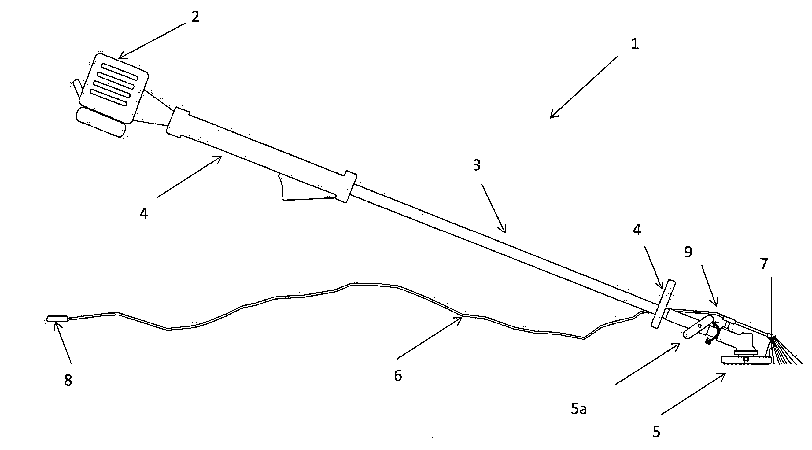
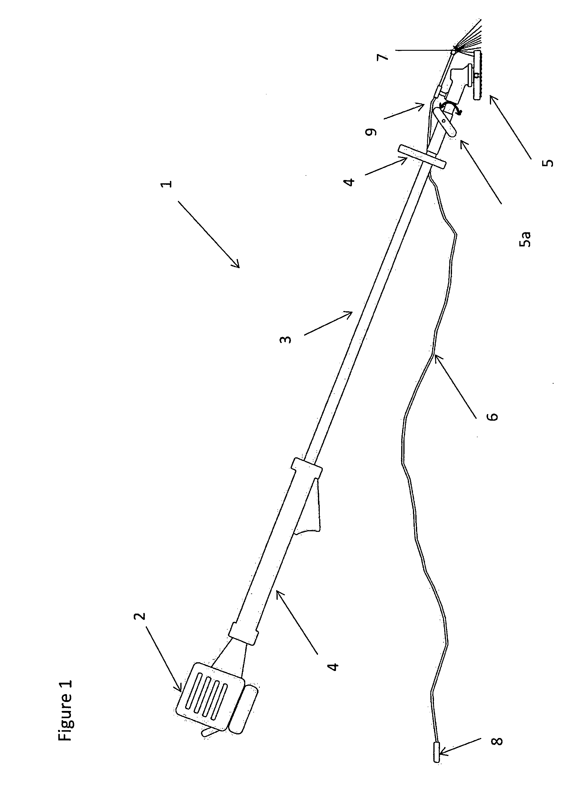
[0111]FIG. 1 shows a side view of an abrasive apparatus as provided in accordance with a preferred embodiment of the invention.

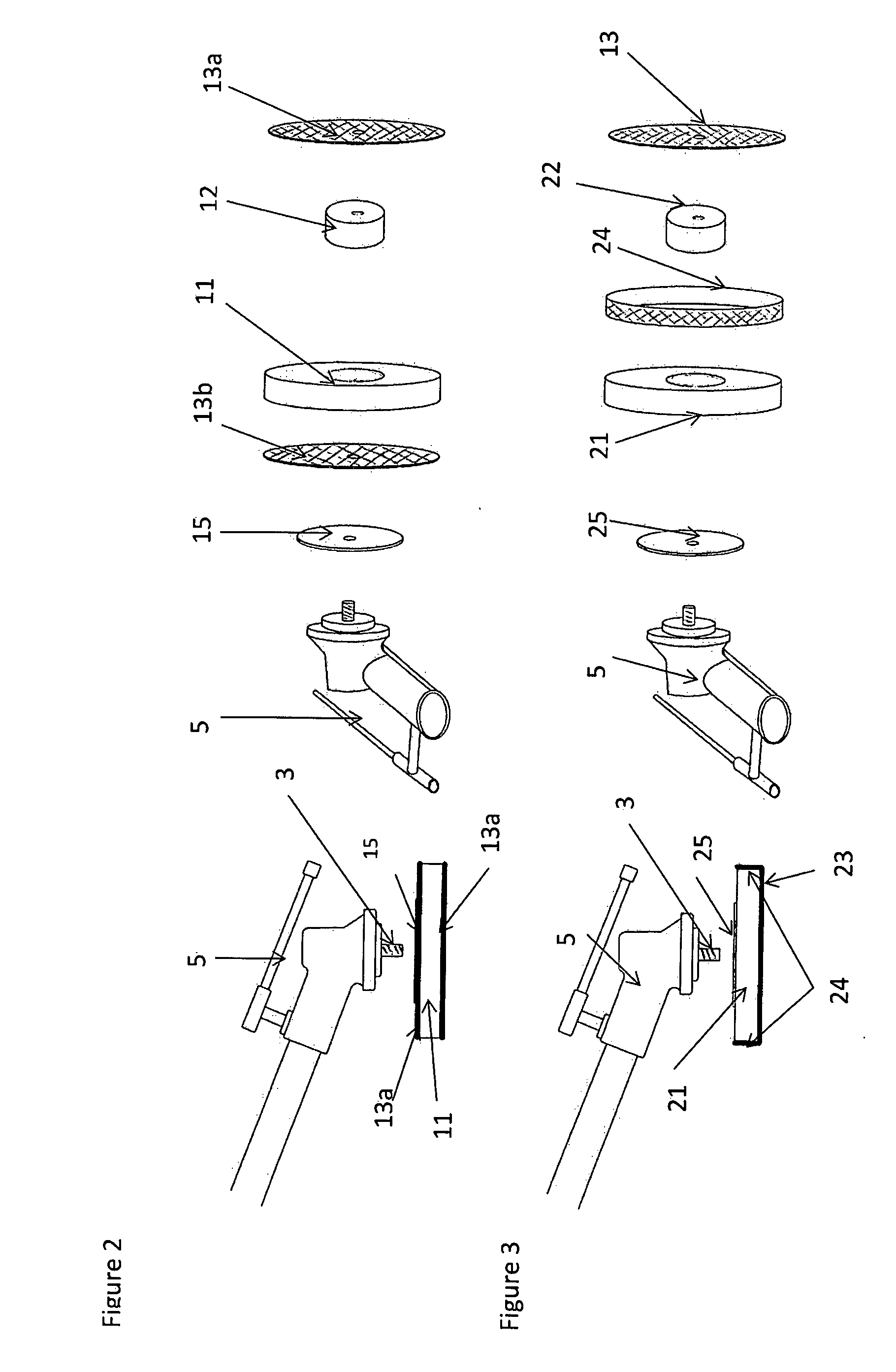
[0112]The apparatus 1 incorporates a drive system, shown in this embodiment as a 45 cc petrol engine 2 linked to an extended internal drive shaft 3 with a set of handles 4 extending to the sides of the drive shaft. The drive shaft 3 terminates in a working head 5 where this working head is arranged to receive and connect to an abrasive attachment as discussed with respect to FIGS. 2 through 6. The working head 5 is engaged to the end of the internal drive shaft by a rotatable gear box coupling 5a. This coupling allows the orientation of the working head to be adjusted relative to the shaft by 90 degree intervals.

[0113]When the apparatus is used to abrade or sand a surface the petrol engine 2 is adapted to rotate portions of the drive shaft 3 to rotate an abrasive attachment associated with the working head 5.

[0114]When the apparatus is used a fluid supply co...


PUM


Abstract

Provided is an abrasive apparatus with a drive shaft terminating with a working head, where this working head is removably attach to an abrasive attachment. Also provided is a drive system arranged to rotate the drive shaft, the drive system being connected to the drive shaft distal from the working head. The abrasive apparatus also includes at least one fluid supply conduit having an inlet and at least one outlet, with the at least one outlet being located adjacent to the working head of the drive shaft and arranged to deliver fluid to the abrasive attachment and / or an immediate working area.

Description

FIELD OF THE INVENTION[0001]This invention relates to improvements in respect of abrasive apparatus and components thereof. In particular the present invention may provide a powered device used as a sanding machine or similar to apply and move an abrasive component or material on a surface. Also within the scope of the invention is a removable abrasive head which may in some embodiments be employed with the abrasive apparatus referenced in respect of this invention, or may alternatively be used with existing prior art sanding machinery.[0002]The invention has particular applicability in applications where large surface areas are to be sanded and preferably where the dispersal of sanding dust is to be controlled while minimising heat build up in the surface being worked.BACKGROUND OF THE INVENTION[0003]Powered sander or abrasive machines are well known forms of technology which are normally configured for use in bench top applications. These types of machines are usually electrically...

Claims


Application Information

Patent Timeline
IPC IPC(8): B24B23/00B24B23/02
CPCB24B23/02B24B23/005B24B7/184B24B55/02B24D5/00B24D7/00
Inventor HAYWOOD, JOHN ANTHONY
Owner ALDERSON NZ
Learn More