
Machine tool having scattering prevention cover

a technology of anti-scattering and machine tools, which is applied in the direction of manufacturing tools, metal-working machine components, metal working apparatuses, etc., can solve the problems of no description about where and how the non-scattering chips are stored

Active Publication Date: 2014-12-25
FANUC LTD
View PDF2 Cites 11 Cited by
  • Summary
  • Abstract
  • Description
  • Claims
  • Application Information

AI Technical Summary

Benefits of technology

The present invention provides a machine tool with a scattering prevention cover that can collect chips and cutting fluid while minimizing their scattering near the table. The machine tool can also discharge the collected chips and cutting fluid to a cutting fluid treatment unit. This helps to improve the efficiency of the machine tool and reduces the risk of injury to operators from the scattering of chips and fluid.

Problems solved by technology

However, there is no description about where the non-scattering chips are stored and how these chips are treated.
However, this technique is applied to a machine tool that has only one movement axis, and there is no description about application of the technique to a machine tool that has three movement axes (X-, Y-, and Z-axes).

Method used


Image

  • Machine tool having scattering prevention cover
  • Machine tool having scattering prevention cover
  • Machine tool having scattering prevention cover

Examples


Embodiment Construction

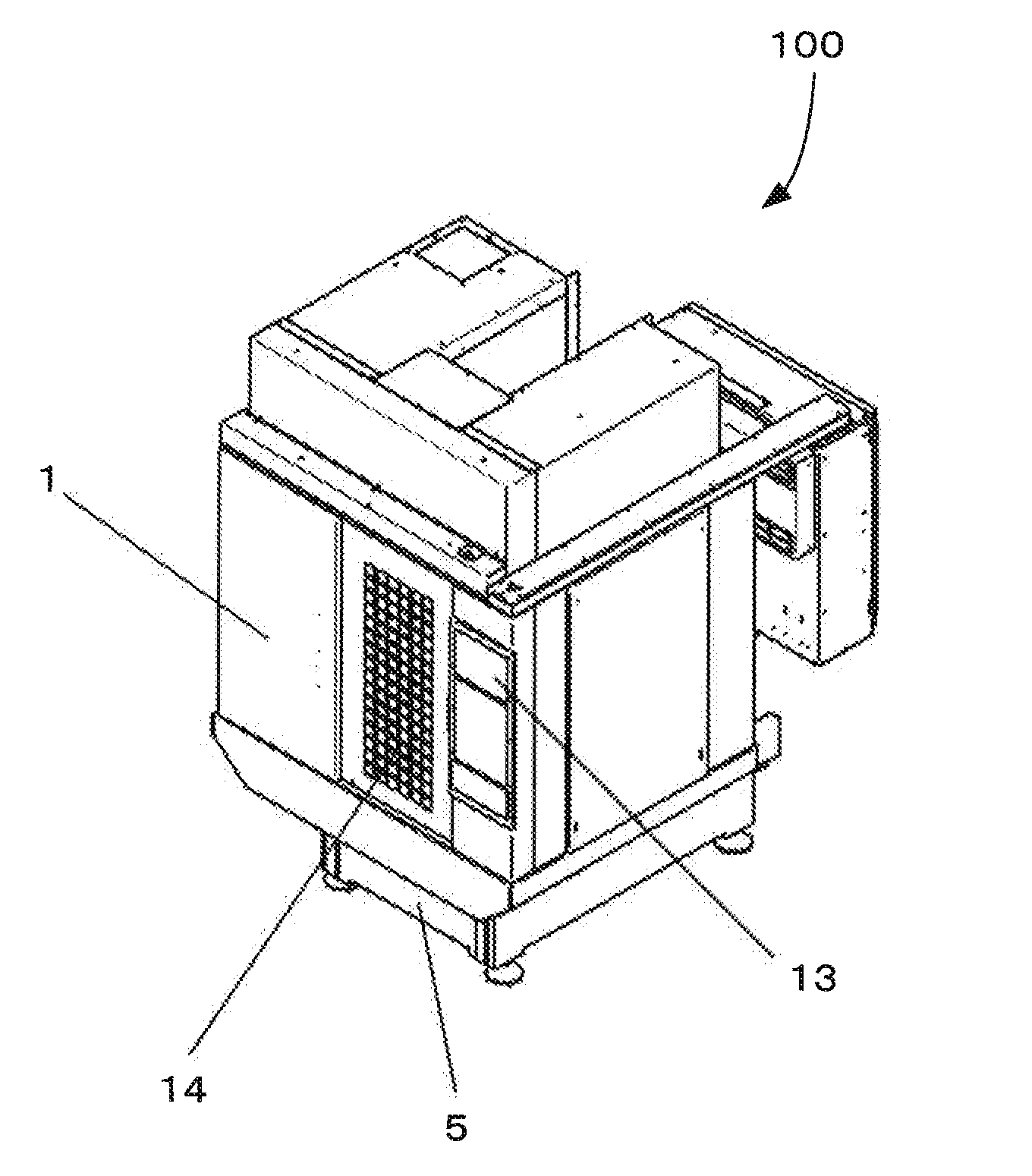
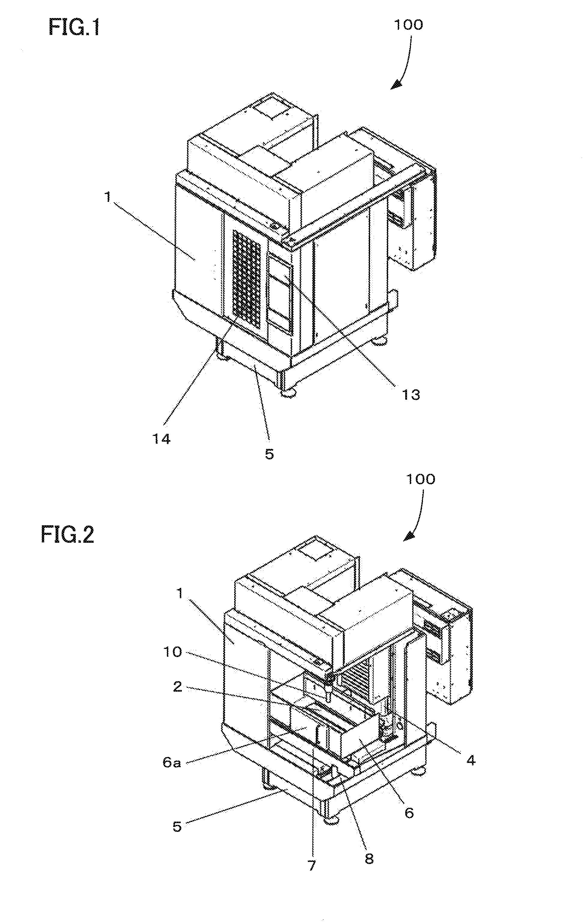
[0021]In a machine tool 100, a machining area formed on the upper part of a bed 5 is covered with a splash guard 1 as shown in FIG. 1. On a side of the splash guard 1, an opening is provided to take a workpiece in and out, and an open / close door 14 is installed in the opening in an openable manner. A control unit 13 with a display that controls the machine tool 100 is installed in the vicinity of the open / close door 14 of the splash guard 1.

[0022]A column 4 with a spindle 9 installed is erected on the bed 5. The column 4 is located at the rear of a saddle 3, and the open / close door 14 is located at the front of the saddle 3. A tool 10 is attached to the spindle 9. The spindle 9 is controlled liftably with respect to a table 2 (that is, movably in the Z-axis direction).

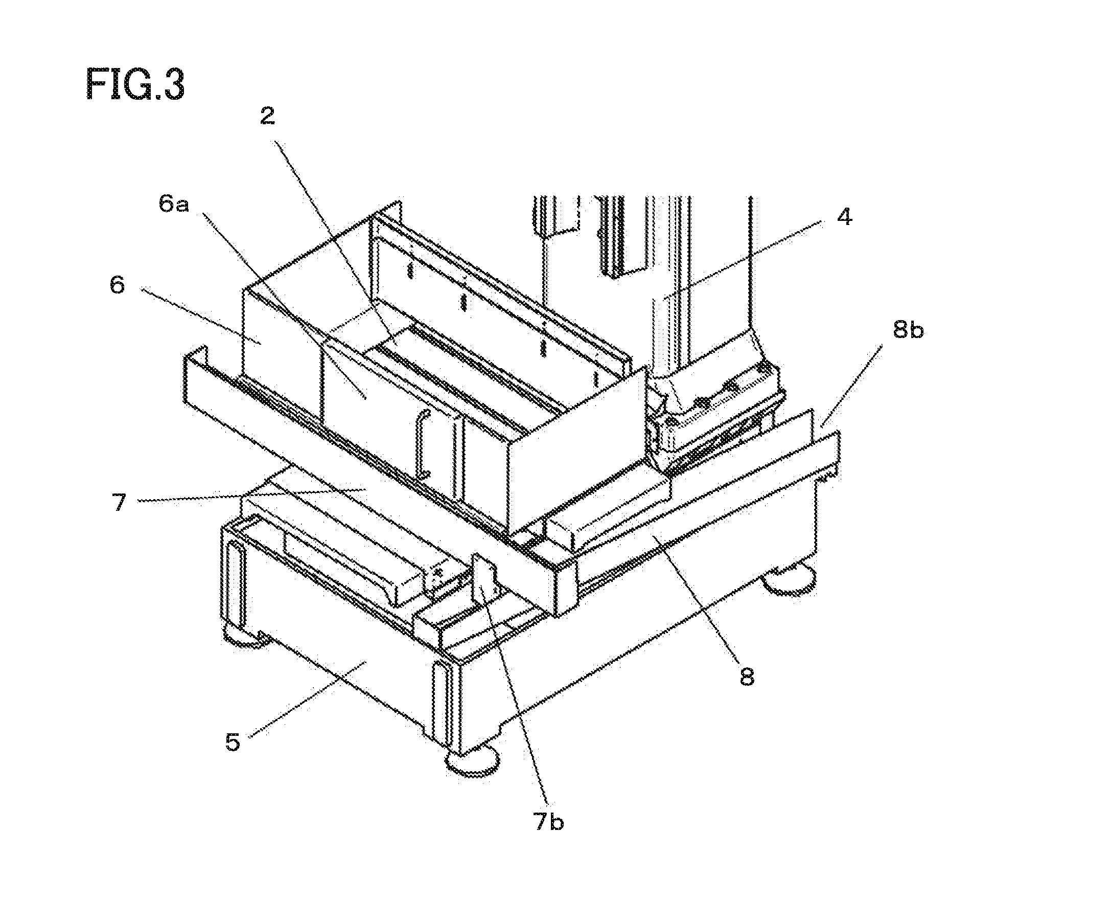
[0023]The saddle 3 is supported on the bed 5, and the table 2 is supported on the saddle 3. A workpiece or machining jig is placed on the table 2. The saddle 3 moves over the bed 5 in the X-axis direction, and the tabl...


PUM

PropertyMeasurementUnit
accelerationaaaaaaaaaa
sizeaaaaaaaaaa
areaaaaaaaaaaa

Abstract

A machine tool has a saddle moving over a bed and a table moving over the saddle. A scattering prevention cover that receives chips generated and a cutting fluid supplied during machining of a workpiece placed on the table is fixed to the table. A first flow path fixed to the saddle receives the chips and cutting fluid discharged from the scattering prevention cover, and a second flow path fixed to the bed receives and discharges the chips and cutting fluid discharged from the first flow path.

Description

BACKGROUND OF THE INVENTION[0001]1. Field of the Invention[0002]The present invention relates to a machine tool having a scattering prevention cover that prevents scattering of chips and a cutting fluid throughout the inside of a splash guard when the machine tool is used.[0003]2. Description of the Related Art[0004]Typically, as a prevention against scattering of chips generated and a cutting fluid supplied to a workpiece (cutting portion) during machining of the workpiece, a machining area is covered with a splash guard or a covering component, screening component, shielding component, or the like is set around the workpiece to suppress scattering of the chips and cutting fluid (see Japanese Patent Application Laid-Open No. 2002-283180 and Japanese Patent Application Laid-Open No. 2012-236268, for example).[0005]Japanese Patent Application Laid-Open No. 2002-283180 discloses a technique by which a shielding component for suppressing scattering of chips on a table is provided, in a...

Claims


Application Information

Patent Timeline
Patent Type & Authority Applications(United States)
IPC IPC(8): B23Q11/00B23Q15/007B23Q11/08
CPCB23Q11/0042B23Q15/007B23Q11/08Y10T409/30392Y02P70/10B23Q15/12
Inventor INAGUCHI, YUUZOU
Owner FANUC LTD
Learn More