
Insulation inspection instrument

a technology of inspection instrument and insulating layer, which is applied in the direction of instruments, dynamo-electric machine testing, dynamo-electric machines, etc., can solve the problems of inability to meet the requirements of continuous testing

Active Publication Date: 2014-12-18
GM GLOBAL TECH OPERATIONS LLC
View PDF4 Cites 6 Cited by
  • Summary
  • Abstract
  • Description
  • Claims
  • Application Information

AI Technical Summary

Benefits of technology

The present invention is about a tool called a continuity tester that is used to inspect the insulation on the stator windings in an electric machine. It includes a power supply, a brush with conductive bristles, and an A / D converter. The brush is placed against the exposed windings and if there is a loss of insulation, the potential at the input of the A / D converter drops, which can be detected. The tool can be used either manually or automatically to position the brush against the windings. Its technical effect is to provide an effective and efficient method for inspecting the insulation on stator windings in electric machines.

Problems solved by technology

During handling, the stator may be inadvertently bumped or rubbed against assembly equipment and other things, where nicks, cuts, abrasions and other defects sometimes occur in the insulation of the stator windings, which could expose the conductive part of the winding.
For example, once the stator is assembled, the process of positioning the rotor within a central bore of the stator may damage the stator windings at various locations.
Such defects in the insulation of the stator windings sometimes affect machine performance and could result in an unacceptable shorter machine life.
Such an inspection operation is obviously labor intensive, and is subject to the limitations of the technician.

Method used


Image

  • Insulation inspection instrument
  • Insulation inspection instrument
  • Insulation inspection instrument

Examples


Embodiment Construction

[0012]The following discussion of the embodiments of the invention directed to a continuity tester is merely exemplary in nature, and is in no way intended to limit the invention or its applications or uses. For example, as discussed herein, the continuity tester of the invention has particular application for identifying defects in the insulation of stator windings of an electric machine. However, as will be appreciated by those skilled in the art, the continuity tester of the present invention may have application for testing other devices.

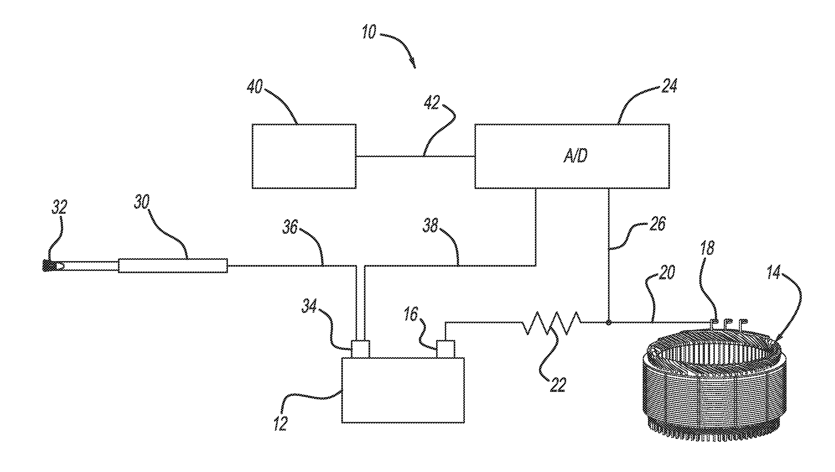
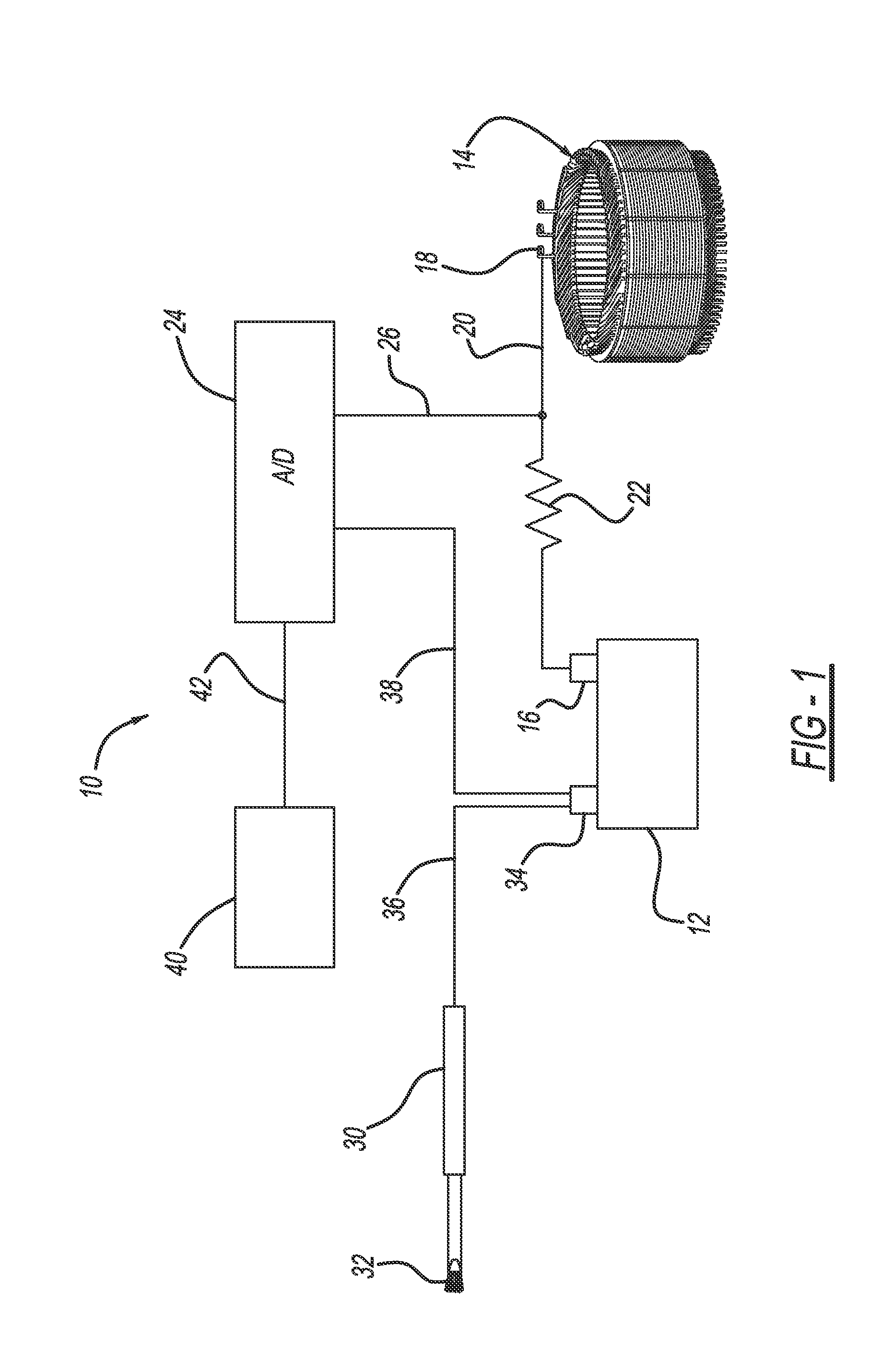
[0013]FIG. 1 is a schematic block diagram of a continuity tester 10 including a power source, such as a battery 12. As will be discussed in detail below, the continuity tester 10 is being used to detect defects in the insulation of stator windings in an electric machine stator 14. The battery 12 can provide any suitable voltage level for a particular continuity test. In one non-limiting embodiment, the battery 12 provides 24 volts as being a pot...


PUM


Abstract

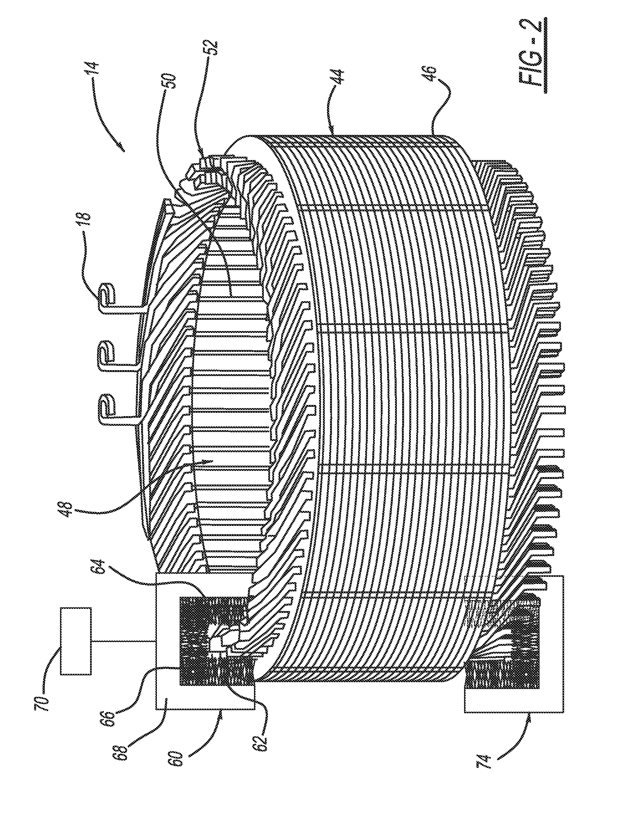
A continuity tester that has particular application for inspecting the insulation on the stator windings in an electric machine. The continuity tester includes a power supply, a brush having conductive bristles, and an analog-to-digital (A / D) converter. One terminal of the power supply is electrically coupled to the brush and another terminal of the power supply is electrically coupled to the A / D converter and the stator being tested. The conductive brush is selectively positioned against the exposed windings of the stator, and if an electrical circuit is formed as a result of loss of insulation, the potential at the input of the A / D converter drops, which can be detected. In one embodiment, the conductive brush is a manual brush that is moved across the stator windings, and in alternate embodiments the conductive brush is specially configured to be positioned against the conductive windings in an automated process.

Description

BACKGROUND OF THE INVENTION[0001]1. Field of the Invention[0002]This invention relates generally to a continuity tester and, more particularly, to a continuity tester including a specially configured conductive brush that has particular application for inspecting insulation damage on stator windings in an electric machine.[0003]2. Discussion of the Related Art[0004]Various types of electric machines are employed in vehicles to provide certain vehicle operations. For example, electric vehicles or electric hybrid vehicles employ traction motors that are often three-phase electric machines including a stator having a series of circumferentially disposed slots and a rotor having a series of circumferentially disposed conductors. Electrical windings are provided within the stator slots in a configuration to provide the three separate circuits for the three phases, where the windings may include conductive bars positioned in the slots. The conductive bars include an outer insulating layer...

Claims


Application Information

Patent Timeline
IPC IPC(8): G01R31/34
CPCG01R31/34G01R31/346H02K15/00
Inventor PERRY, THOMAS A.CAMPBELL, JOHN D.
Owner GM GLOBAL TECH OPERATIONS LLC
Learn More