
Job management system for a fleet of autonomous mobile robots

a mobile robot and job management technology, applied in the direction of vehicle position/course/altitude control, process and machine control, instruments, etc., can solve the problems of increasing the risk of physical injury or death of human operators, increasing the risk of damage to expensive or rare equipment and inventory, and exposing the transported items and manufacturing equipment to higher contamination levels, so as to achieve favorable status and configuration, the effect of improving the quality of work

Active Publication Date: 2014-12-11
ORMON CORP
View PDF5 Cites 278 Cited by
  • Summary
  • Abstract
  • Description
  • Claims
  • Application Information

AI Technical Summary

Benefits of technology

The patent describes a system that helps choose the best mobile robot for a job based on its compatibility with the job location and operation. The system analyzes the status and configuration of each robot and determines which one has the better chances of completing the job. The main advantage is that the system helps improve the efficiency and accuracy of selecting the best robot for the job, making it easier to work with and improve the overall performance of the fleet.

Problems solved by technology

Using human operators to transport items from one location to another location in the physical environment in this manner has many disadvantages, including for example: problems keeping track of the physical locations of the transported items; difficulties moving items around the factory or warehouse according to schedules dictated by automated components in the order processing system; exposing the human operators to increased risks of physical injury or death; increased risk of damage to expensive or rare equipment and inventory; and exposing the transported items and manufacturing equipment to higher contamination levels caused by the presence of the human operators.
The disadvantages of using conveyor belts and overhead transport systems include: being constrained to a fixed (linear) delivery path; not being able to deliver products to down-stream workstations if an upstream workstation in the process is out of service; and having to move and / or make expensive changes to the conveyor belt system or overhead transportation system if a single workstation in the process has to be moved to a different location.
But the utility and flexibility of conventional fleets of mobile robots for these environments has heretofore been very limited due to several significant operational shortcomings, including for instance: (1) having to install markers, rails, wires or grids in the floors, ceilings and / or walls of the facilities so that the fleet of mobile robots can use them for navigation; (2) the mobile robots in the fleet having little or no ability to independently determine their routes to specified destinations (i.e., to navigate autonomously); (3) the mobile robots in the fleet having little or no ability to modify a selected route to a specified destination in response to encountering other non-stationary objects, including people and other mobile robots while driving to the specified destination; and (4) the mobile robots in the fleet having little or no ability to automatically determine and carry out a particular task or operation upon arriving at a specified destination, to name but a few examples.
But factories, warehouses and distribution centers are usually not laid out in perfectly straight lines because they tend to expand outward from center in multiple directions and at different rates according to need and funding.
Therefore, the existing mobile robot fleet solutions tend to be less useful, less efficient and less productive in situations where the tools and workstations that the fleet of mobile robots have to service have varying shapes and sizes, or are physically offset from one another.
Because of the above-described limitations and shortcomings associated with conventional mobile robot fleets, the conventional job management systems, which control and manage the fleets of mobile robots, have also been very limited in utility and flexibility.
The result is that, although useful to some degree, the conventional job management systems for fleets of mobile robots do not permit truly “intelligent” delegation, handling and completion of job requests within a given operating environment.
Another problem associated with existing automated warehouse management systems involving fleets of mobile robots is that they tend to use a fleet of homogeneous mobile robots, all having the same set of functions, capabilities and constraints.
As a result, conventional job management systems tend to distribute job requests to the mobile robots in the fleet based on a very limited set of criteria, such as the mobile robot's current position in the physical environment relative to the specified job location for the job request.

Method used


Image

  • Job management system for a fleet of autonomous mobile robots
  • Job management system for a fleet of autonomous mobile robots
  • Job management system for a fleet of autonomous mobile robots

Examples


examples

[0172]Following are several examples to demonstrate usage of the various commands. Lines that start with “QueueUpdate:” are messages that are broadcasted by the Job Management System.

##cel examples

QueueCancel Examples

[0173]

Example #1—cancelling a Pending item: QueueUpdate: PICKUP11 JOB11 10 Pending None Goal “t” None 12 / 19 / 2011 06:50:45 None None 0 queuecancel goal t abc QueueCancel: PICKUP11 JOB11 10 Cancelling None Goal “w20” None 12 / 16 / 2011 13:19:07 None None abc QueueUpdate: PICKUP11 JOB11 10 Cancelled None Goal “t” None 12 / 19 / 2011 06:50:45 12 / 19 / 2011 06:50:58 0Example #2—cancelling an InProgress item QueueUpdate: PICKUP8 JOB8 10 InProgress None Goal “w20” “MT-490” 12 / 16 / 2011 13:19:07 None None 0 queuecancel goal w20 abc QueueCancel: PICKUP8 JOB8 10 Cancelling None Goal “w20” None 12 / 16 / 2011 13:19:07 None None abc QueueUpdate: PICKUP8 JOB8 10 Interrupted None Goal “w20” None 12 / 16 / 2011 13:19:07 None None 0 QueueUpdate: PICKUP8 JOB8 10 Cancelled None Goal “w20” None 12 / 16 / 2011 13:19:07 12 / 16 / 2011 13:19:13 0Example #3—cancelling an InProgress item with reason QueueUpdate: PICKUP8 JOB8 10 InProgress None Goal “w20” “MT-490” 12 / 16 / 2011 13:19:07 None None 0 queuecancel goal w2...

##p examples

QueuePickup Examples

[0174]

Example #1—queuepickup with priority and JobID queuepickup z 11 xyz queuepickup goal “z” with priority 11, id PICKUP13 and job_id xyz successfully queued QueueUpdate: PICKUP13 xyz 11 Pending None Goal “z” None 12 / 19 / 2011 06:54:18 None None 0 QueueUpdate: PICKUP13 xyz 11 InProgress UnAllocated Goal “z” None 12 / 19 / 2011 06:54:18 None None 0 QueueUpdate: PICKUP13 xyz 11 InProgress Allocated Goal “z” None 12 / 19 / 2011 06:54:18 None None 0 QueueUpdate: PICKUP13 xyz 11 InProgress BeforePickup Goal “z” “Adept_Telepresence_Robot” 12 / 19 / 2011 06:54:18 None None 0 QueueUpdate: PICKUP13 xyz 11 InProgress EveryBefore Goal “z” “Adept_Telepresence_Robot” 12 / 19 / 2011 06:54:18 None None 0 QueueUpdate: PICKUP13 xyz 11 InProgress Before Goal “z” “Adept_Telepresence_Robot” 12 / 19 / 2011 06:54:18 None None 0 QueueUpdate: PICKUP13 xyz 11 InProgress Driving Goal “z” “Adept_Telepresence_Robot” 12 / 19 / 2011 06:54:18 None None 0 QueueUpdate: PICKUP13 xyz 11 InProgress After Goal “z” “Adept_T...


PUM


Abstract

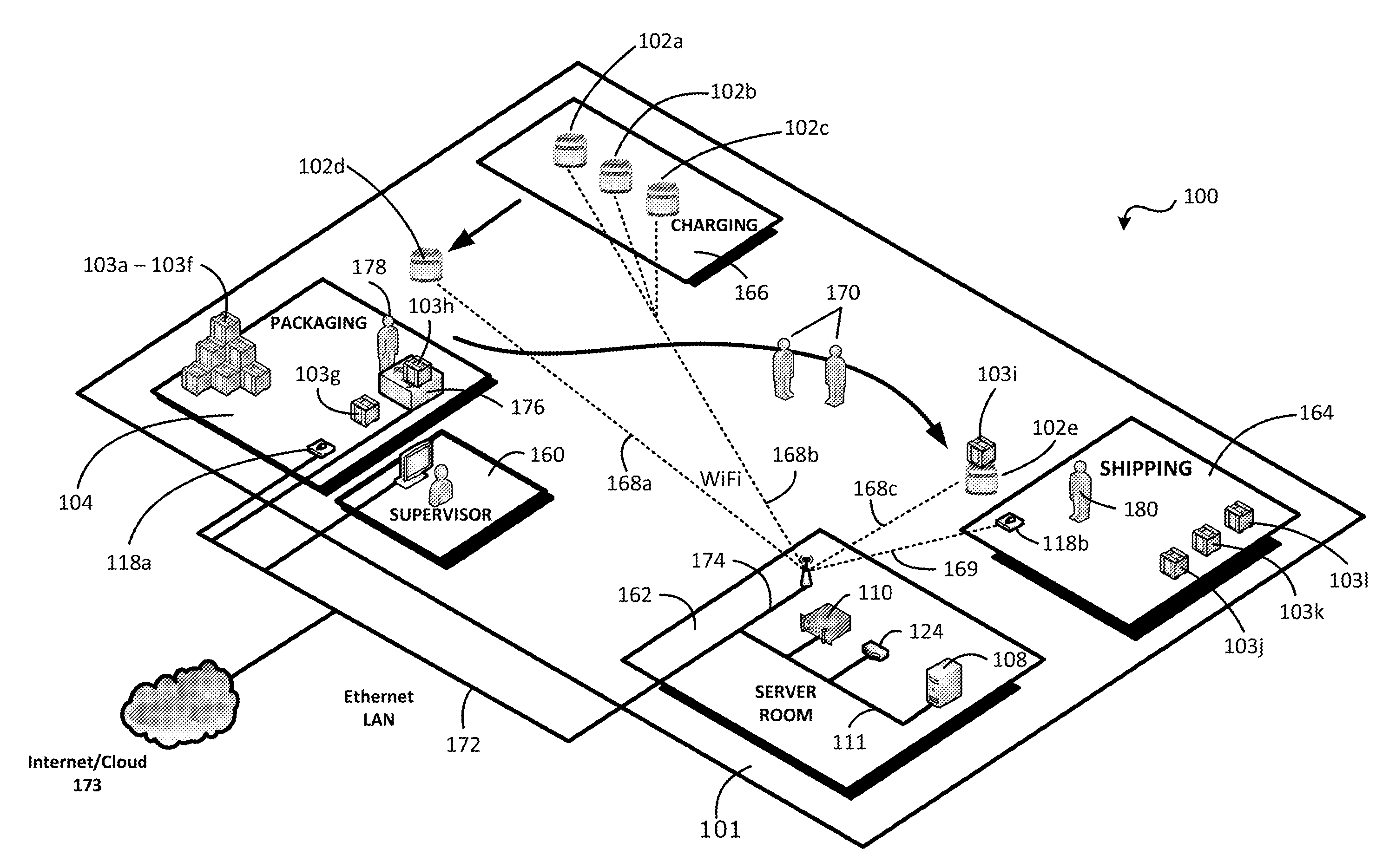
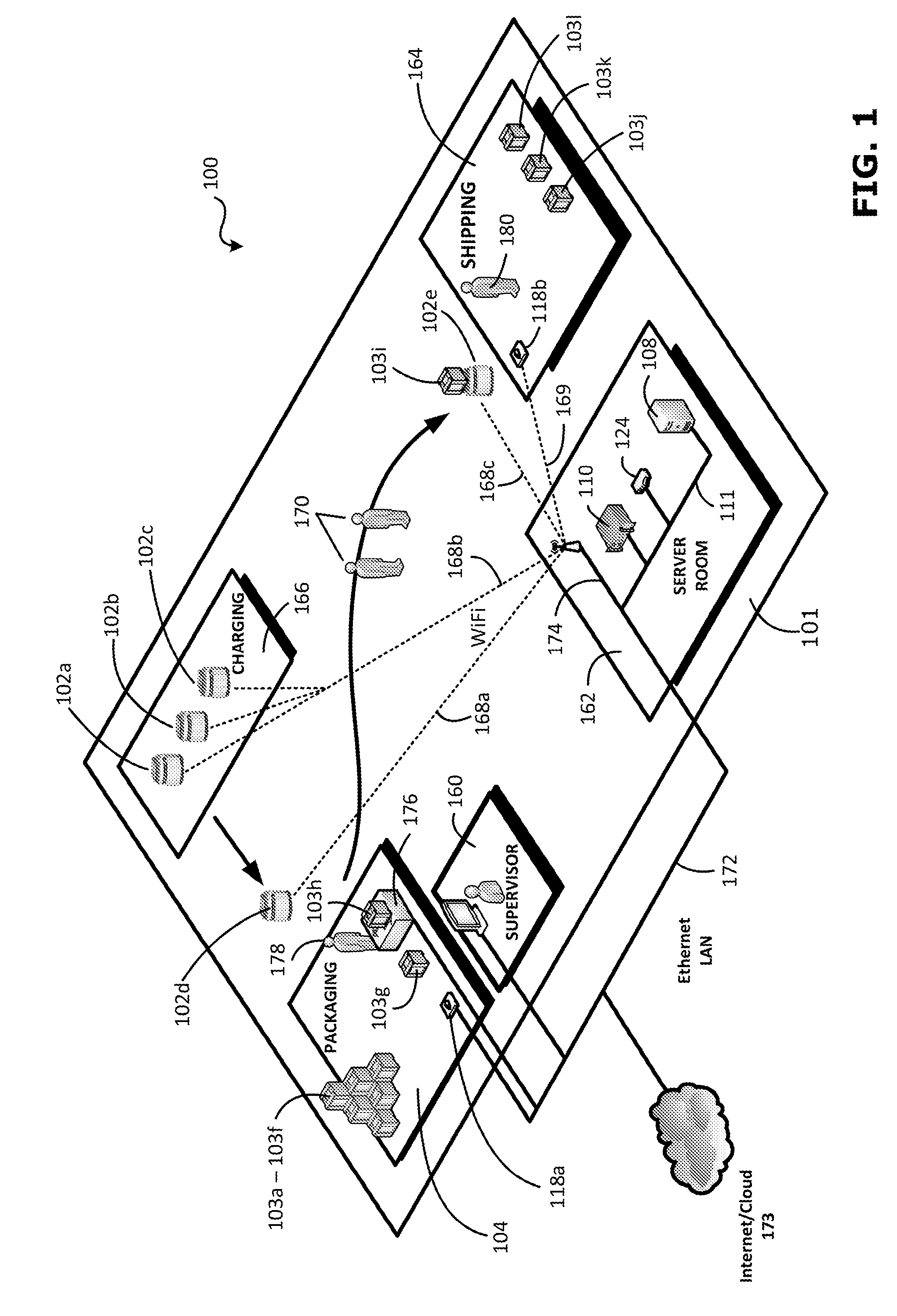
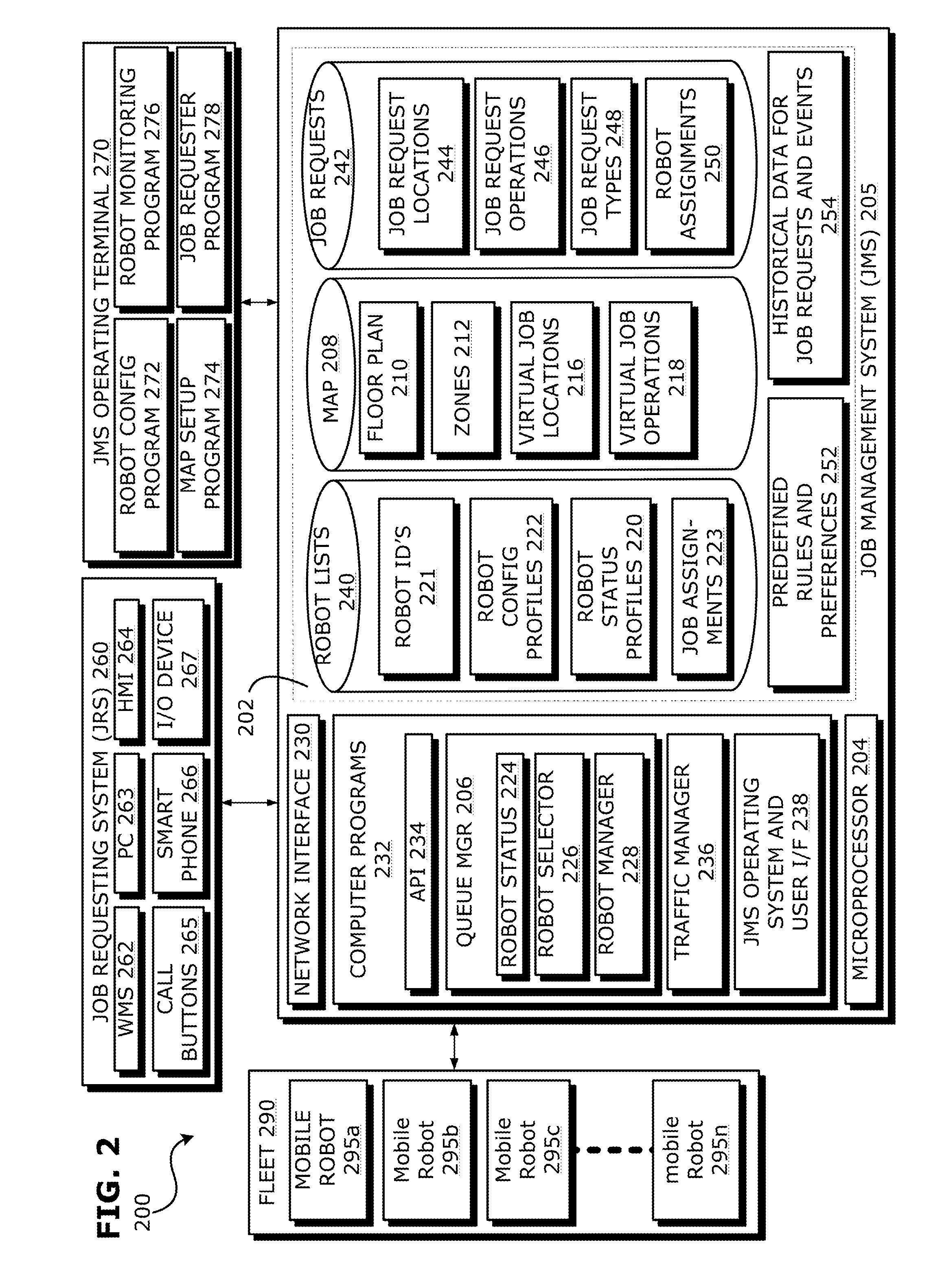
The Job Management System (JMS) of the present invention processes job requests in an automated physical environment, such as a factory, hospital, order processing facility or office building, wherein the job requests are handled by a fleet of autonomously-navigating mobile robots. The JMS includes a map defining a floor plan, a set of virtual job locations and a set of one or more virtual job operations associated with virtual job locations. The JMS automatically determines the actual locations and actual job operations for the job requests, and intelligently selects a suitable mobile robot to handle each job request based on the current status and / or the current configuration for the selected mobile robot. The JMS also sends commands to the selected mobile robot to cause the mobile robot to automatically drive the actual job location, to automatically perform the actual job operations, or both.

Description

FIELD OF THE INVENTION [0001]The present invention relates to systems and methods for processing job requests in an automated physical environment. More particularly, the present invention is directed to a job management system that receives and processes job requests in an automated physical environment, such as a warehouse, factory, hospital, office building, mail or online order processing facility, or similar enterprise, where the physical environment includes a fleet of mobile robots for automated handling of the job requests.RELATED ART[0002]In a typical order processing environment, merchandise may be transported around a distribution center or warehouse by human operators pushing, pulling or driving mobile containers, carriers, carts, cargo bins or fork lifts from one location to another. Using human operators to transport items from one location to another location in the physical environment in this manner has many disadvantages, including for example: problems keeping tra...

Claims


Application Information

Patent Timeline
Patent Type & Authority Applications(United States)
IPC IPC(8): G06Q10/06
CPCY10S901/01G06Q10/063114G05D1/024G05D1/0246G05D1/0255G05D1/0274G05D1/0297G16H40/20
Inventor VESTAL, MATTHEWLAFARY, MATTHEWSTOPERA, PETER
Owner ORMON CORP
Learn More