
Plasma processing apparatus and plasma processing method

a plasma processing and plasma technology, applied in the direction of electrical apparatus, basic electric elements, electric discharge tubes, etc., can solve the problems of high reflected power, difficult matching, and plasma impedance as viewed from the radio-frequency bias to change, and achieve the effect of stable supply

Active Publication Date: 2014-12-11
HITACHI HIGH-TECH CORP
View PDF6 Cites 78 Cited by
  • Summary
  • Abstract
  • Description
  • Claims
  • Application Information

AI Technical Summary

Benefits of technology

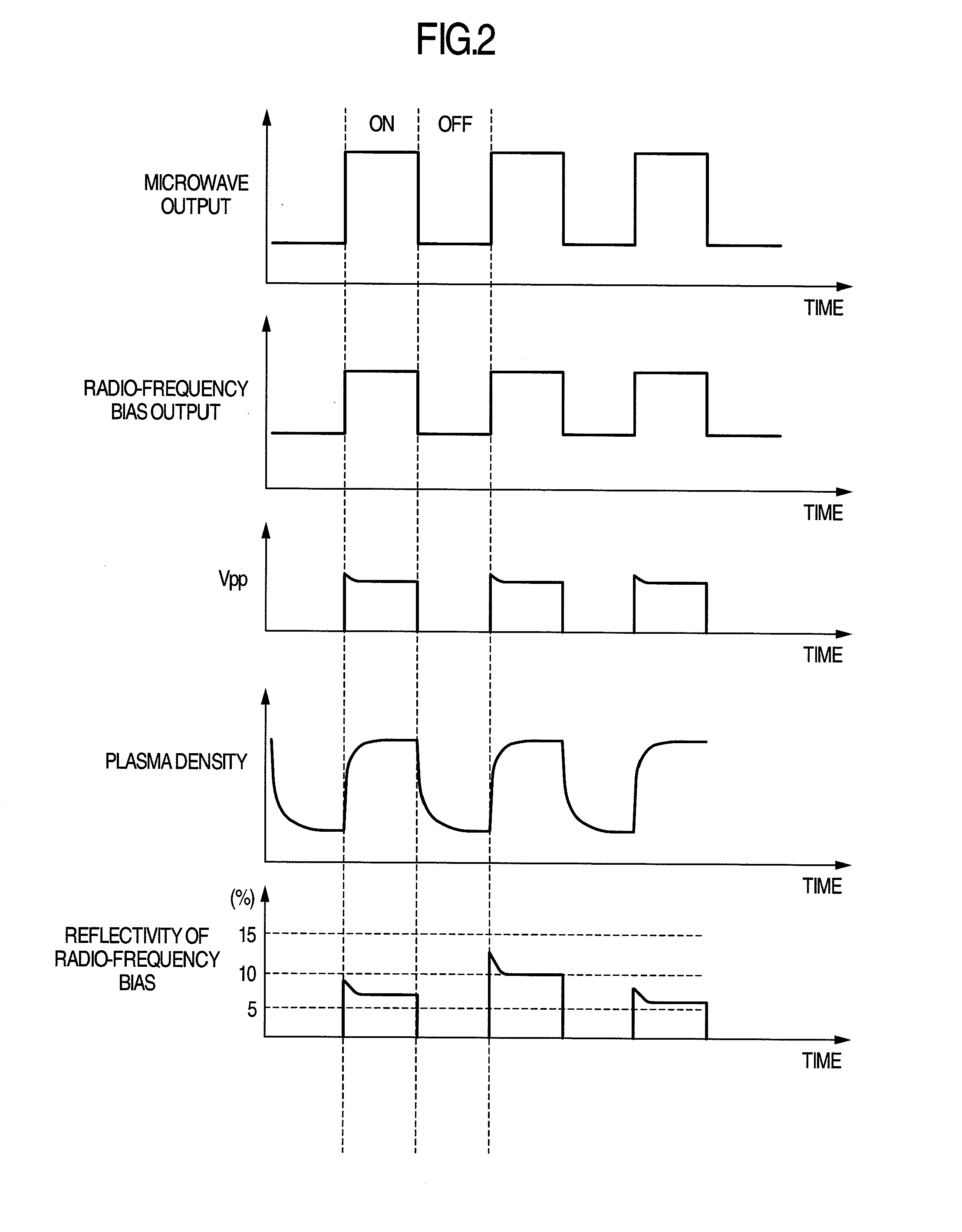
The patent text discusses the measurement of reflectivity of a radio-frequency bias in a plasma generation system. The result shows that the reflectivity is 5% or less of the radio-frequency bias output value when using a continuous wave output method. This reflectivity level does not affect the process performance and does not damage the power supply. The reflectivity is calculated by dividing the reflected power of the radio-frequency bias by its output power. The text also mentions that the microwave output is off during certain periods, which leads to a low plasma density and has a negligible effect on etching performance. It is advantageous to match the radio-frequency bias during periods when the plasma density is stable, as this greatly influences etching performance.

Problems solved by technology

On the other hand, in the pulsed plasma scheme, a transient time until stabilization of the plasma density exists every period and, when the radio-frequency bias synchronized with the pulsed plasma is applied, the plasma density changes due to repetition of on and off, thereby causing the plasma impedance as viewed from the radio-frequency bias to change and rendering matching difficult.
In this case, as shown in FIG. 2, there occurs a phenomenon that the reflected power becomes high and the reflection value is also unstable.
When the reflected power value is large, there arises a problem that a difference between an actual applied power to a wafer and a set power value increases, so that high-accurate control cannot be performed.
Also, since the reflected power returns to the power supply, the power supply may be damaged.
In this case, the etching processing result may also be unstable.

Method used


Image

  • Plasma processing apparatus and plasma processing method
  • Plasma processing apparatus and plasma processing method
  • Plasma processing apparatus and plasma processing method

Examples


Embodiment Construction

[0038]Embodiments for implementing the present invention are now described with reference to the accompanying drawings. FIG. 5 schematically illustrates a longitudinal section of a microwave plasma etching apparatus of an ECR scheme according to an embodiment of the present invention. At the upper part of a vacuum chamber 101 having the opened top, a shower plate 102 made of quartz for introducing etching gas into the vacuum chamber 101 and a dielectric window 103 made of quartz are disposed and a processing chamber 104 is formed by hermetically sealing them.

[0039]To the shower plate 102, a gas supply device 105 for causing the etching gas to flow is connected. Further, a vacuum evacuation device 106 is connected to the vacuum chamber 101 via an on-off valve for evacuation 117 and a variable evacuation speed valve 118. The inside of the processing chamber 104 is decompressed by making the on-off valve for evacuation 117 open and driving the vacuum evacuation device 106 and brought i...


PUM

PropertyMeasurementUnit
reflectivityaaaaaaaaaa
frequencyaaaaaaaaaa
frequencyaaaaaaaaaa

Abstract

In a plasma processing apparatus including a first radio-frequency power supply which supplies first radio-frequency power for generating plasma in a vacuum chamber, a second radio-frequency power supply which supplies second radio-frequency power to a sample stage on which a sample is mounted, and a matching box for the second radio-frequency power supply, the matching box samples information for performing matching during a sampling effective period which is from a point of time after elapse of a prescribed time from a beginning of on-state of the time-modulated second radio-frequency power until an end of the on-state and maintains a matching state attained during the sampling effective period from after the end of the on-state until a next sampling effective period.

Description

BACKGROUND OF THE INVENTION[0001]The present invention relates to a plasma processing apparatus and a plasma processing method and, more particularly, to a plasma processing apparatus and a plasma processing method appropriate to perform high-accuracy etching processing using plasma in order to process a sample such as a semiconductor device.[0002]Heretofore, as a method of processing the surface of a semiconductor device, there is known an apparatus of etching the semiconductor device with plasma. A related art is described here by taking a plasma etching apparatus with an electron cyclotron resonance (hereinafter, abbreviated to ECR) scheme as an example.[0003]In the ECR scheme, plasma is generated by a microwave in a vacuum chamber to which a magnetic field is externally applied. Electrons undergo cyclotron motion by the magnetic field and the frequency thereof and the frequency of the microwave can be resonated to generate the plasma efficiently. In order to accelerate ions impi...

Claims


Application Information

Patent Timeline
Patent Type & Authority Applications(United States)
IPC IPC(8): H01L21/3065H01L21/67
CPCH01L21/67069H01L21/3065H01J37/32082H01J37/32165H01J37/32183H01J37/32192H01J37/3244H01J2237/334
Inventor MORIMOTO, MICHIKAZUYASUI, NAOKIOHGOSHI, YASUO
Owner HITACHI HIGH-TECH CORP
Learn More