
Display device and method for operating the display device

a display device and display technology, applied in the direction of electric digital data processing, instruments, computing, etc., can solve the problems of affecting the image luminance, and affecting the display quality, so as to achieve satisfactory image luminance and satisfactory display quality

Active Publication Date: 2014-12-04
SAMSUNG DISPLAY CO LTD
View PDF0 Cites 3 Cited by
  • Summary
  • Abstract
  • Description
  • Claims
  • Application Information

AI Technical Summary

Benefits of technology

This approach substantially minimizes crosstalk, providing satisfactory display quality and maintaining image luminance without the need to turn off the backlight, thus enhancing the overall display performance for both 2D and 3D images.

Problems solved by technology

When the images for adjacent frames are different from each other, if the response speed of the electric optical active layer (e.g., a liquid crystal layer) is not sufficiently high, the images for the adjacent frames may be seen at the same time and accordingly may be blurred and unclear.
Particularly, in the case where a motion picture is displayed, blurring may increase due to crosstalk.
Insufficient response speed of the electric optical active layer may cause substantial crosstalk, which may substantially deteriorate display quality.

Method used


Image

  • Display device and method for operating the display device
  • Display device and method for operating the display device
  • Display device and method for operating the display device

Examples


Embodiment Construction

[0073]The present invention will be described more fully hereinafter with reference to the accompanying drawings, in which embodiments of the invention are shown. As those skilled in the art would realize, the described embodiments may be modified in various different ways, all without departing from the spirit or scope of the present invention.

[0074]Various embodiments are described herein below, including methods and techniques. It should be kept in mind that the invention might also cover an article of manufacture that includes a non-transitory computer readable medium on which computer-readable instructions for carrying out embodiments of the inventive technique are stored. The computer readable medium may include, for example, semiconductor, magnetic, opto-magnetic, optical, or other forms of computer readable medium for storing computer readable code. Further, the invention may also cover apparatuses for practicing embodiments of the invention. Such apparatus may include circu...


PUM


Abstract

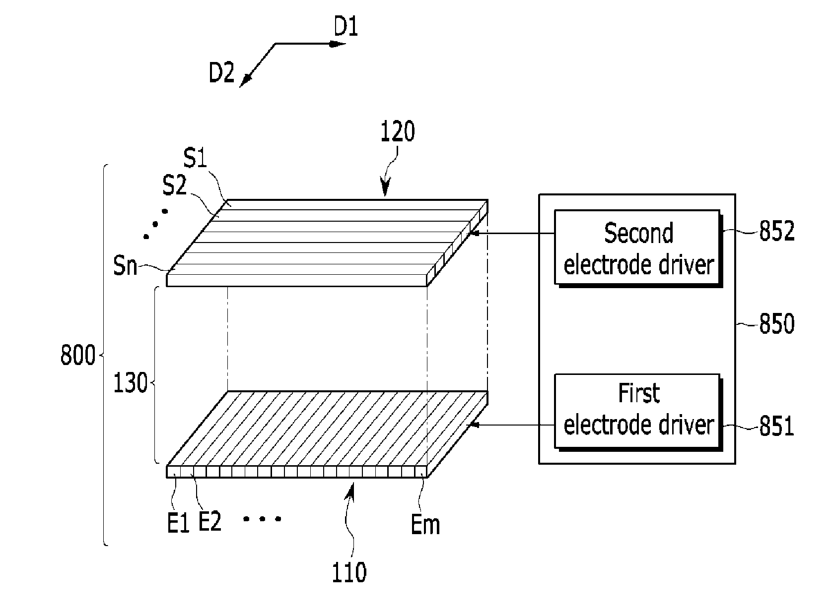
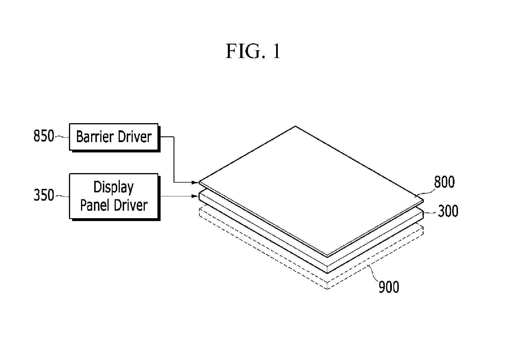
A display device includes a display panel configured to receive a first-frame image signal for displaying a first-frame image in a first frame. The display panel is further configured to receive a second-frame image signal for displaying a second-frame image in a second frame that immediately follows the first frame such that the display panel appears to display a transition region associated with a boudary between a portion of the first-frame image and a portion of the second-frame image and moving in a moving direction. The display device further includes an optical effect layer and electrode sets. The electrode sets respectively overlap different portions of the optical effect layer and are configured for sequentially starting affecting the different portions of the optical effect layer such that the optical effect layer appears to display a light-blocking section that moves in the moving direction and overlaps the transition region.

Description

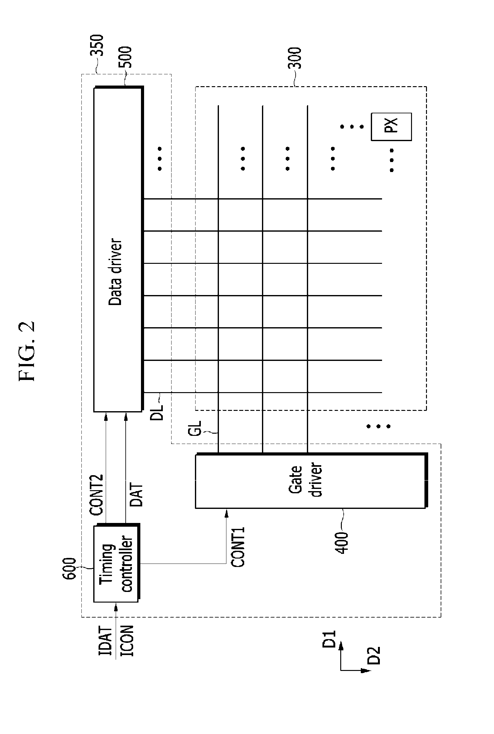
CROSS-REFERENCE TO RELATED APPLICATION[0001]This application is a continuation application of U.S. patent application Ser. No. 13 / 663,357 filed Oct. 29, 2012, which claims priority to and the benefit of Korean Patent Application No. 10-2012-0077802 filed in the Korean Intellectual Property Office on Jul. 17, 2012, the entire contents of which are incorporated herein by reference.BACKGROUND OF THE INVENTION[0002](a) Field of the Invention[0003]The present invention relates to a display device and a method for driving the display device.[0004](b) Description of the Related Art[0005]A display device may include a plurality of pixels for displaying an image, a plurality of display signal lines connected to a switching element included in a pixel, a gate driver applying a gate-on voltage and a gate-off voltage to a gate line of the display signal lines to turn-on / off the switching element of the pixel, and a data driver applying a data voltage to a data line of the display signal lines t...

Claims


Application Information

Patent Timeline
Patent Type & Authority Applications(United States)
IPC IPC(8): G09G3/30G02B30/31
CPCG09G2310/0275G09G3/30H04N13/341H04N13/315H04N13/398G02B30/24G02B30/31G09G3/36G02B30/27
Inventor KIM, KANG-MINKIM, KWAN-HOODAKE, RYOTAJEON, SANG MINKIM, SEON KIKIM, JIN HWANKIM, TAE HYUNGSONG, A RAMYU, SEUNG JUNJUNG, JAE WOOCHO, JUNG-HYUN
Owner SAMSUNG DISPLAY CO LTD
Learn More