
Method and device for touch identification, and touch screen

a technology of touch identification and touch screen, applied in the field of computer touch and control, can solve the problems of loss of touch point data and performance degradation, inability to detect touch events, and inability to accurately determine the position of these touch regions based on shielded scanning rays, so as to improve the effectiveness of touch data, avoid loss of effective touch data, and improve the accuracy of touch identification.

Active Publication Date: 2014-12-04
SHANGHAI JINGYAN ELECTRONICS TECH
View PDF2 Cites 6 Cited by
  • Summary
  • Abstract
  • Description
  • Claims
  • Application Information

AI Technical Summary

Benefits of technology

The present disclosure provides a method and device for better identifying touch regions on a touch screen. By scanning the screen using a direct-axis scanning mode and an off-axis scanning mode with multiple angles, the method avoids loss of effective touch data on the screen. The device employs confidence levels of intersections of scanning axes to greatly improve accuracy of touch identification. This method is easy to realize, low in cost, and can be applied to a wide range of devices.

Problems solved by technology

Due to the gaps in the grid, when a touch point, particularly a fine touch point (for example, formed by a fine contact terminal such as a finger of a minor, or a nib), falls into the gaps, the point cannot shield infrared scanning rays between a pair of infrared emitter and receiver, that is, the touch event cannot be detected because of a lack of direct-axis data.
Therefore, in conventional solutions, a valid touch point may not be detected due to a scanning environment, which may result in a loss for touch point data and performance degradation.
Scanning rays are emitted from the plurality of angles, thus, even a very small touch region may be detected, which avoids loss of effective touch data on a touch screen, in consideration that a touch region has a certain area on the touch screen, to some touch regions which have small area, accurate positions of these touch regions may not be accurately determined based on shielded scanning rays.
In existing techniques, a scanning axis has a certain width, thus, intersections of scanning axes may not be obtained easily and touch regions may not be identified accurately.

Method used


Image

  • Method and device for touch identification, and touch screen
  • Method and device for touch identification, and touch screen
  • Method and device for touch identification, and touch screen

Examples


Embodiment Construction

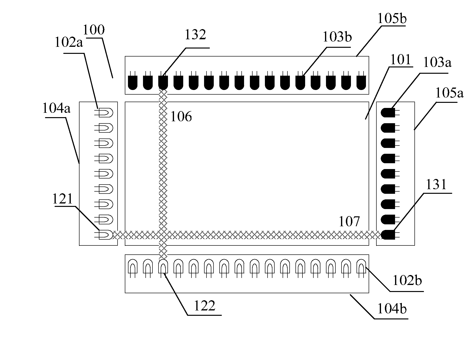
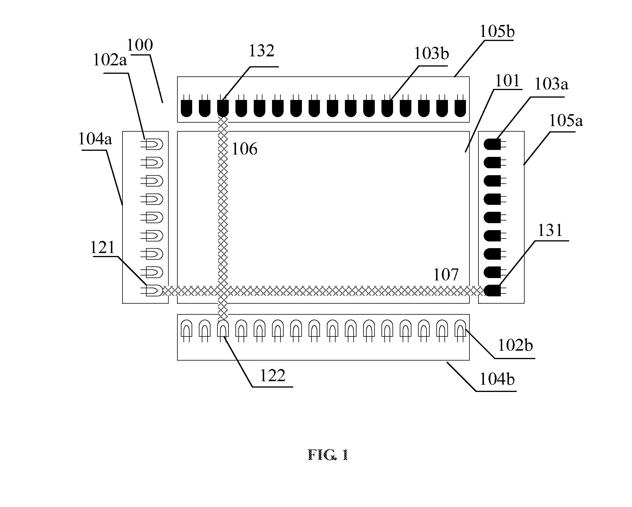
[0036]A touch device 100 is illustrated in FIG. 1. The touch device 100 takes a shape of rectangle and arrays of emitting components (102a and 102b) and arrays of receiving components (103a and 103b) are installed at surrounding edges of the touch device 100. A touch screen 101 may be a display region of a computer display or a projector screen. The emitting components correspond to the receiving components in a one-to-one manner and constitute a plurality of emitting-receiving pairs. In practice, the arrays of emitting components 102a and 102b are mounted on emitting plates 104a and 104b respectively, and each emitting component is an emitting lamp which is adapted to emit infrared scanning rays. The arrays of receiving components 103a and 103b are mounted on receiving plates 105a and 105b respectively, and each receiving component is a receiving lamp which is adapted to receive infrared scanning rays.

[0037]A method for touch identification based on the touch device 100 includes fo...


PUM


Abstract

Method and device for touch identification, and a touch screen are provided. The method includes: performing an axial scanning on a touch screen, and when a touch region is detected, recording scanning axes with scanning rays shielded; corresponding to the detected touch region, according to axial directions, obtaining sets of intersections of the scanning axes with scanning rays shielded; calculating a confidence level for each of the intersection in each set of intersections; and performing a coordinate fusion to all the sets of intersections which correspond to the touch region based on the confidence levels to obtain positions of the touch region. The device includes a scanning record unit, an intersection unit, a calculation unit and a coordinate fusion unit. In the present disclosure, an effective touch region on a touch screen may be better identified.

Description

CROSS-REFERENCE TO RELATED APPLICATIONS[0001]The present application claims priority to Chinese patent application No. 201310214627.2, filed on May 31, 2013, and entitled “METHOD AND DEVICE FOR TOUCH IDENTIFICATION, AND TOUCH SCREEN”, and the entire disclosure of which is incorporated herein by reference.FIELD OF THE DISCLOSURE[0002]The present disclosure generally relates to computer touch and control, and more particularly, to a method and device for touch identification, and a touch screen.BACKGROUND OF THE DISCLOSURE[0003]Infrared touch screens, as a kind of computer touch screen, are humanized in inputting and thus have a broad application prospect. For example, infrared touch screens are easy to be installed and maintained, and have strong anti-explosion capability and high reliability, so they are widely used in devices in current various fields.[0004]An infrared touch screen basically includes a plurality of couples of an infrared emitter and an infrared receiver installed i...

Claims


Application Information

Patent Timeline
Patent Type & Authority Applications(United States)
IPC IPC(8): G06F3/041
CPCG06F3/041G06F3/0418G06F3/0421
Inventor ZHANG, YUMINGZHAO, LEIXU, JIAO
Owner SHANGHAI JINGYAN ELECTRONICS TECH
Learn More