
Autonomous smart grid demand measurement system and method

Inactive Publication Date: 2014-11-20
THE POWERWISE GRP
View PDF3 Cites 18 Cited by
  • Summary
  • Abstract
  • Description
  • Claims
  • Application Information

AI Technical Summary

Benefits of technology

The patent discusses a way to make electric grids more stable by using a probability model and energy savings system with special devices. These devices help regulate voltage at points of energy consumption. This technology can make electric grids better at handling fluctuations in demand and reduce the amount of energy wasted.

Problems solved by technology

As the depletion of Earth's natural resources continues and the costs for such resources rapidly increase, power generation and energy conservation has become an increasingly important issue with governments, businesses, and consumers.
The problem of power distribution is of great concern as it involves existing infrastructure that is usually inadequate for properly distributing power and not readily suitable to be improved upon.
This problematical situation is manifested by “brown outs” wherein a nominal AC voltage cannot be maintained in the face of a grid / generation overload.
This method usually results in a wide disparity of voltages available to consumers in homes and / or business.
Shedding power as heat results in wasted energy that is paid for by the customer.
By contrast, if the voltage is significantly less than the optimum voltage, then the appliance may not work properly.
If the grid voltage is not boosted at the transformer or at the beginning of the distribution grid, the voltage may be too low at the end of the grid to properly power customer appliances.
If an electric grid becomes unstable, the electric power utility may lose control of the electric grid and the ability to reliably deliver electric power.
A failure may include a brown-out, a rolling black-out, or a complete electric grid power failure.
However, larger instabilities are problematic and can cause the electric grid to fail.
While electric grid failures can be avoided by reducing the load on the grid, the electric utility has little control over individual consumer demands on the grid.
Attempts to regulate consumer demand that focus on individual electric devices (motors, appliances, lights sources) in a home or business can be expensive and complicated.

Method used


Image

  • Autonomous smart grid demand measurement system and method
  • Autonomous smart grid demand measurement system and method
  • Autonomous smart grid demand measurement system and method

Examples


Embodiment Construction

[0062]Various examples are provided herein. While specific examples are discussed, it should be understood that this is for illustration purposes only. A person skilled in the relevant art will recognize that other components and configurations may be used without departing from the spirit of the disclosure.

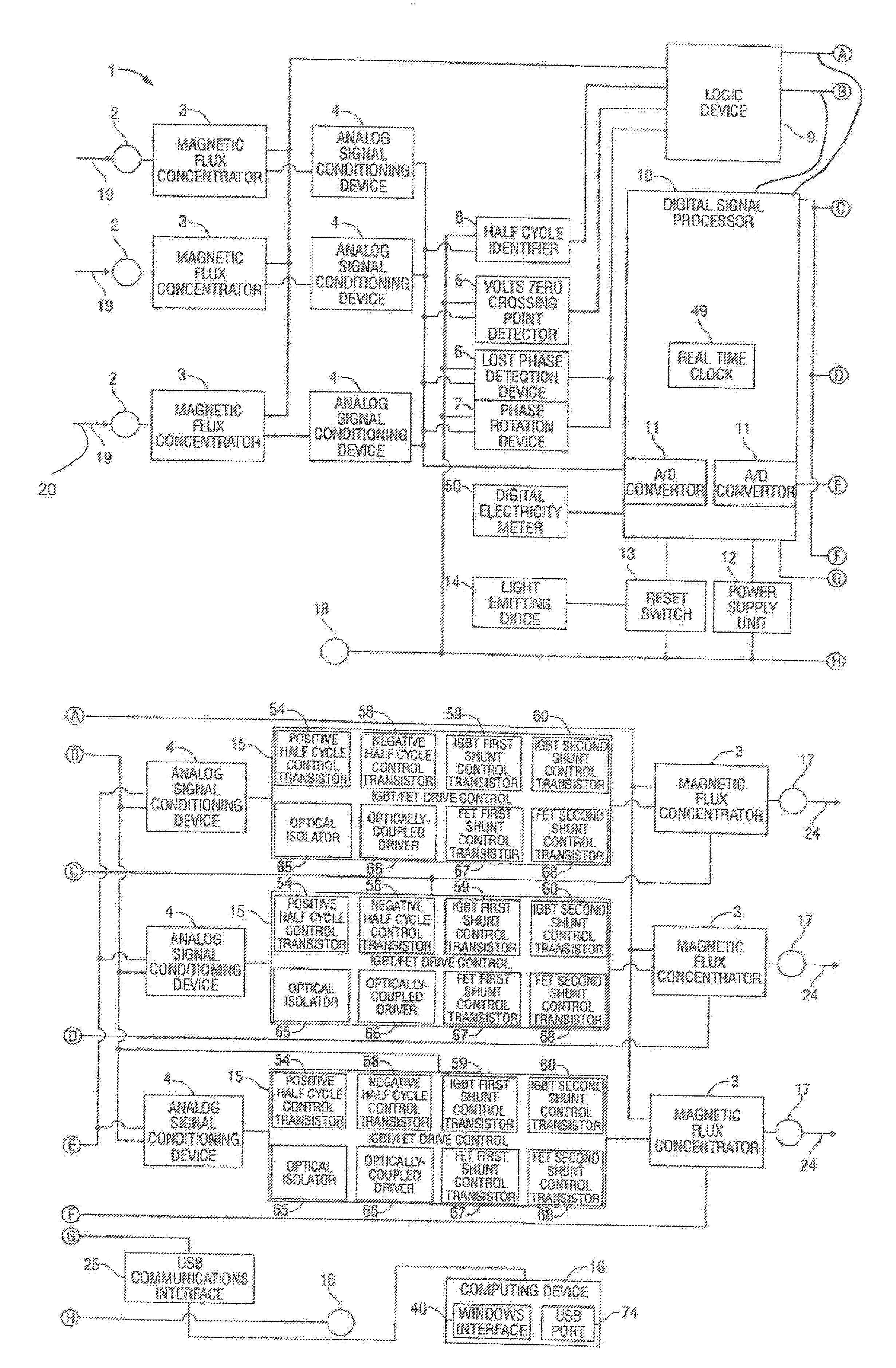
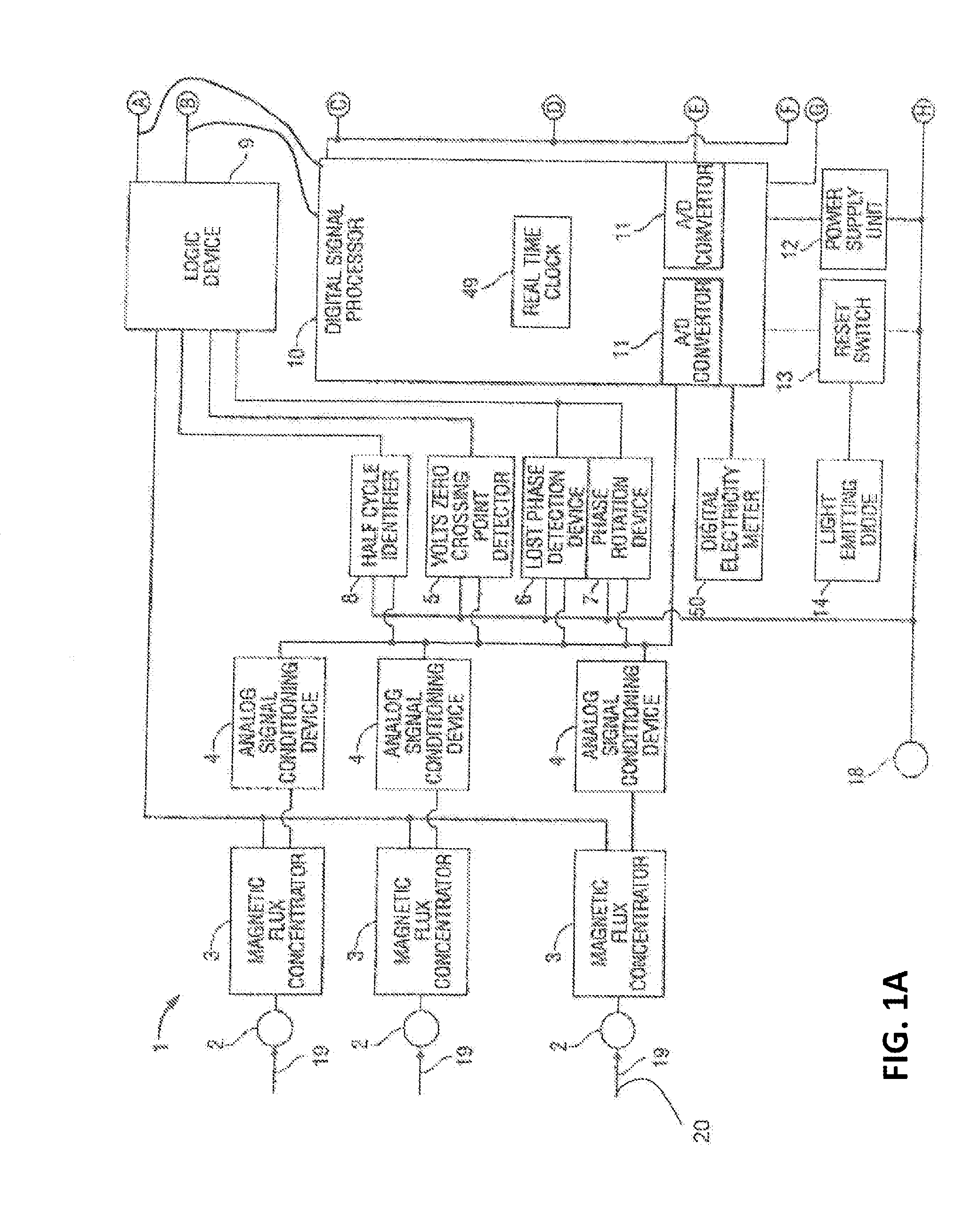
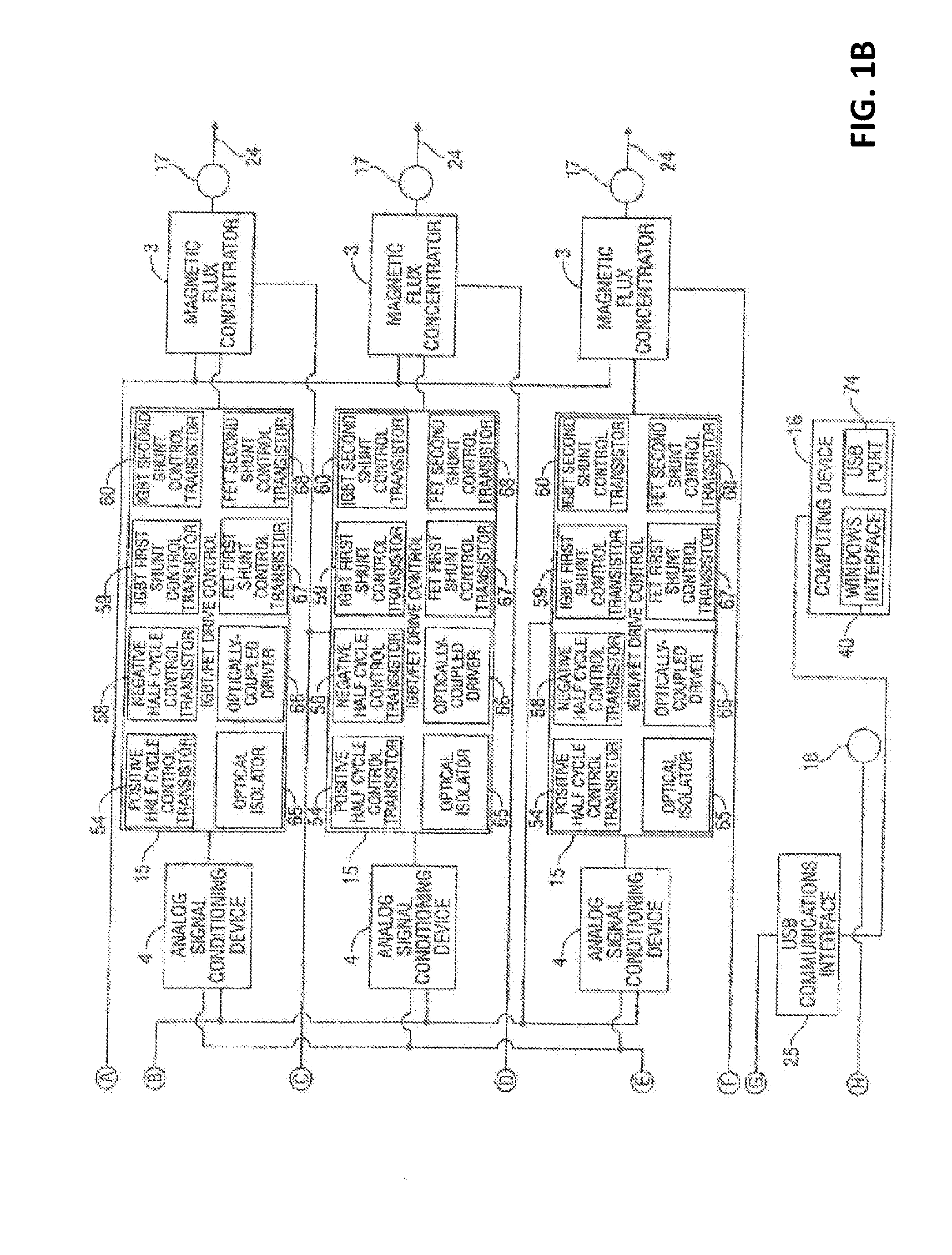
[0063]Systems and method are provided for improving electric utility grid power stability. In one example, systems and method are provided for improving electric utility power grid stability by employing a probability model that is implemented by an energy savings device. In one example, the energy savings system uses IGBT / FET devices that are configured to regulate voltage. Furthermore, an insulated gate bipolar transistor / field effect transistor (IGBT / FET) based energy savings device is provided for conserving energy while improving electric utility power grid stability.

[0064]According to one example, self-regulating or autonomous energy savings devices are provided at points o...


PUM


Abstract

An energy savings device, system and method are provided to improve electric utility grid stability by reducing power demand at a point of consumption. The method may include monitoring a power signal characteristic, obtaining a stability parameter for the utility grid, determining a stability condition based on the monitored power signal characteristic and the stability parameter; and regulating, at the point of consumption, an amount of energy received from the utility grid based on the determined stability condition. The system may include an energy savings system in communication with the electric utility grid and a processor and non-transitory computer-readable medium configured to perform the method.

Description

CROSS REFERENCE TO RELATED APPLICATIONS[0001]This application claims priority to U.S. Provisional Application No. 61 / 781,822 filed on Mar. 14, 2013, the complete disclosure of which is incorporated herein by reference.BACKGROUND OF THE DISCLOSURE[0002]1. Field of the Disclosure[0003]This disclosure generally relates to the field of electrical energy savings, and, in particular, energy savings involving voltage regulation.[0004]2. Description of the Art[0005]Since the industrial revolution, the world's consumption of energy has grown at a steady rate. Most power generated and energy consumed is from the combustion of fossil fuels, a nonrenewable natural resource that is rapidly becoming depleted. As the depletion of Earth's natural resources continues and the costs for such resources rapidly increase, power generation and energy conservation has become an increasingly important issue with governments, businesses, and consumers.[0006]In addition to general concerns with power generati...

Claims


Application Information

Patent Timeline
IPC IPC(8): G05F1/66
CPCG05F1/66Y02B70/3225Y04S20/222H02J2310/12H02J3/14
Inventor MANSFIELD, STEPHEN KENNETHMCDONALD, DONALD JAY
Owner THE POWERWISE GRP
Learn More