
Method and system for common-mode-rejection-ratio (CMRR) characterization of an integrated coherent receiver

a receiver and common-mode rejection technology, applied in electromagnetic receivers, electromagnetic transmission, transmission monitoring, etc., can solve the problem that the exact value of intermediate frequencies is not generally known with the same high precision, and achieve the effect of reducing the overall cost of test hardwar

Active Publication Date: 2014-11-20
EXFO
View PDF2 Cites 38 Cited by
  • Summary
  • Abstract
  • Description
  • Claims
  • Application Information

AI Technical Summary

Benefits of technology

The patent proposes a method and system for generating the intermediate frequency using two single-frequency lasers that are mutually slightly offset in wavelength. This eliminates the need for an expensive intensity modulator and rf frequency generator. However, the exact value of the intermediate frequency is not known with the same high precision. To overcome this issue, the patent proposes to retrieve the value of the intermediate frequency from the output electrical signals of the ICR as detected and sampled. Additionally, detection of the electrical output of the ICR under test is made using undersampling which helps in reducing the overall cost of the test hardware. This method and system offer a cost-effective solution for generating the intermediate frequency in optical communication systems.

Problems solved by technology

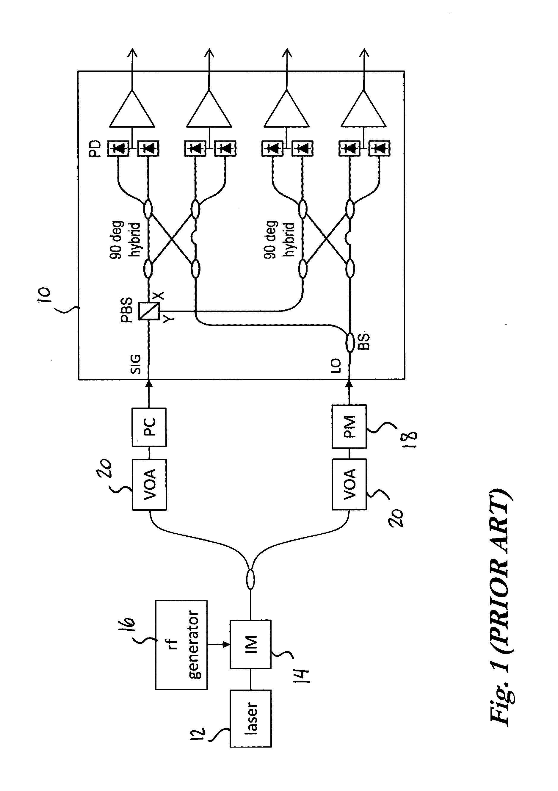
In addition to the generally expensive hardware required for generating sidebands at fIF, the system of Painchaud et al (loc cit) also requires a slowly-varying controllable phase modulator 18 disposed in the optical path before one of the ICR inputs.
However, in the method and system proposed herein, the exact value of the intermediate frequency is not generally known with the same high precision.

Method used


Image

  • Method and system for common-mode-rejection-ratio (CMRR) characterization of an integrated coherent receiver
  • Method and system for common-mode-rejection-ratio (CMRR) characterization of an integrated coherent receiver
  • Method and system for common-mode-rejection-ratio (CMRR) characterization of an integrated coherent receiver

Examples


case 1

[0109] If Δf is small, then direct use of the set values (fIF=fIF,set) has no significant impact on measured ICR parameters to within some predetermined measurement tolerance, and hence there is no need to seek greater accuracy of the measured tone at frequency fIF (e.g. via an algorithmic procedure as outlined with reference to “Case 3” hereinbelow). Here M=Mset.

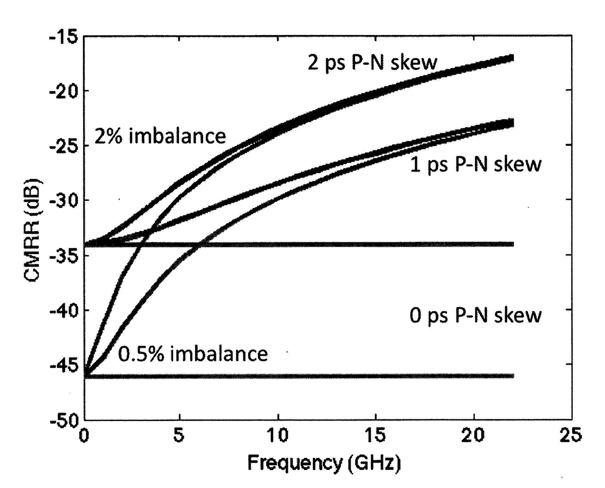
[0110]The CMRR measurement itself is generally not highly dependent on the exact value of fIF. However, other related measurements that may also be performed in the context of ICR characterization might be more stringent in this regard. For instance, measurement of the hybrid phase error is quite sensitive to the value of fIF and hence a systematic offset in fIF may introduce a non-negligible measured phase error, whereas the effect of a randomly-varying offset in fIF normally would be less detrimental, as this randomly-varying offset could be reduced via averaging. FIG. 10 presents the results of a simulation of the IQ-ell...

case 2

[0111] When the uncertainty Δf is very high (e.g. Δf>fs / 2), little or no improvement in the fIF accuracy can be attained via analysis of the Fourier spectra of e.g. the complex IQ field, since the folding ratio (M) associated with the aliasing will often be incorrect. Hence, CMRR evaluation via undersampling would normally not be feasible for this case.

case 3

[0112] If the uncertainty Δf is of a level intermediate to that of Cases 1 and 2 above, i.e. for which direct estimation according to Case 1 would not be fully reliable but for which Δfs / 2, enabling the correct folding ratio M to be estimated in terms of Mset, then the accuracy of the estimated fIF can be improved by Fourier analysis. FIG. 11 shows an example where Δfs / 2 and fIF,set is close to 5fs / 2. Hence, the true fIF may fall either below or above 5fs / 2 (i.e. the corresponding folding ratio may be M=2 or M=3, respectively), as indicated by the shaded frequency range, which extends from (fIF,set−Δf) to (fIF,set+Δf). As a result of aliasing, this true frequency range is folded to an aliased frequency range extending from −fs / 2 to +fs / 2, for the case where in-phase and quadrature-phase signals are simultaneously sampled. (If only one of in-phase and quadrature-phase signals were sampled, then the aliased frequency range would extend only from 0 to +fs / 2.) Since Δfs / 2, there is a “g...


PUM


Abstract

There are provided a method and a system for characterizing the CMRR of an ICR under test, which employ highly coherent light from two continuous-wave (CW) single-frequency lasers whose respective optical frequencies mutually differ by an offset defining an “Intermediate Frequency” (fIF) in the rf electrical baseband. The method involves the coherent mixing of light from these two lasers in the ICR under test. A “tone” in the rf electrical baseband at frequency fIF is generated by the beating of light from the two single-frequency lasers as they interfere on the photodetectors of the ICR. The resulting tone at frequency fIF in the output electrical signals of the ICR is then detected and analyzed to characterize the CMRR of the ICR.

Description

CROSS-REFERENCE TO RELATED APPLICATIONS[0001]This application claims priority under 35 USC §119(e) of U.S. provisional patent application 61 / 824,129 filed May 16, 2013; the specification of which is hereby incorporated by reference.TECHNICAL FIELD[0002]The invention relates to the field of coherent optical detection and more specifically to testing and characterizing the Common-Mode-Rejection-Ratio (CMRR) of Integrated Coherent Receivers (ICR).BACKGROUND OF THE ART[0003]Coherent transmission is increasingly being employed in modern fiber-optic networks, as it is a key enabler in greatly increasing both the spectral efficiency (i.e. number of data bits per Hz of optical spectrum) and the tolerance of links to various transmission impairments (e.g. polarization mode dispersion, chromatic dispersion, etc.). Usually, the spectral efficiency is increased by an additional factor of two by spectrally multiplexing orthogonally-polarized optical signals, an approach referred to as “polarizat...

Claims


Application Information

Patent Timeline
IPC IPC(8): H04B10/073H04B10/64H04B10/61
CPCH04B10/0731H04B10/64H04B10/6151H04B10/614
Inventor WESTLUND, MATHIASSUNNERUD, HENRIK
Owner EXFO
Learn More