
Method and apparatus for 3D imaging a workpiece

Active Publication Date: 2014-11-20
EASTERN KENTUCKY UNIVERSITY
View PDF1 Cites 3 Cited by
  • Summary
  • Abstract
  • Description
  • Claims
  • Application Information

AI Technical Summary

Benefits of technology

The present patent provides methods and systems for three-dimensional virtual reconstruction of a surface of a workpiece by positioning the workpiece between a display screen and an imager, and acquiring multiple images of the workpiece as the display screen sweeps multiple light stripes in different directions. The data from the multiple images is used to determine changes in the width and profile of the light stripes caused by the workpiece, which are then used to calculate the depth value of the workpiece at each pixel position. This allows for the virtual reassembly of the surface of the workpiece. The patent also includes a method for analyzing light reflectance from the workpiece surface and combining it with the transmittance analysis for further refinement of the surface shape. The technical effects of the patent include improved accuracy and efficiency in the virtual reconstruction of workpiece surfaces.

Problems solved by technology

However, even properly preserved acetate negatives deteriorate beyond a point of feasible reading or digitization by conventional techniques.
The negatives decay due to a chemical reaction that releases acetic acid, leaving the base (acetate) and photographic (emulsion) layers unstable.
Physical restoration is possible, but is a complex process requiring physically separating the negative layers and reseating the emulsion layer on a new base layer.
While effective, the process is too time consuming, labor intensive, and costly when considering restoration of large collections.

Method used


Image

  • Method and apparatus for 3D imaging a workpiece
  • Method and apparatus for 3D imaging a workpiece
  • Method and apparatus for 3D imaging a workpiece

Examples


Embodiment Construction

[0024]In the following detailed description of the illustrated embodiments, reference is made to the accompanying drawings that form a part hereof, and in which is shown by way of illustration, specific embodiments in which the invention may be practiced. These embodiments are described in sufficient detail to enable those skilled in the art to practice the invention. Also, it is to be understood that other embodiments may be utilized and that process, reagent, materials, software, and / or other changes may be made without departing from the scope of the present invention.

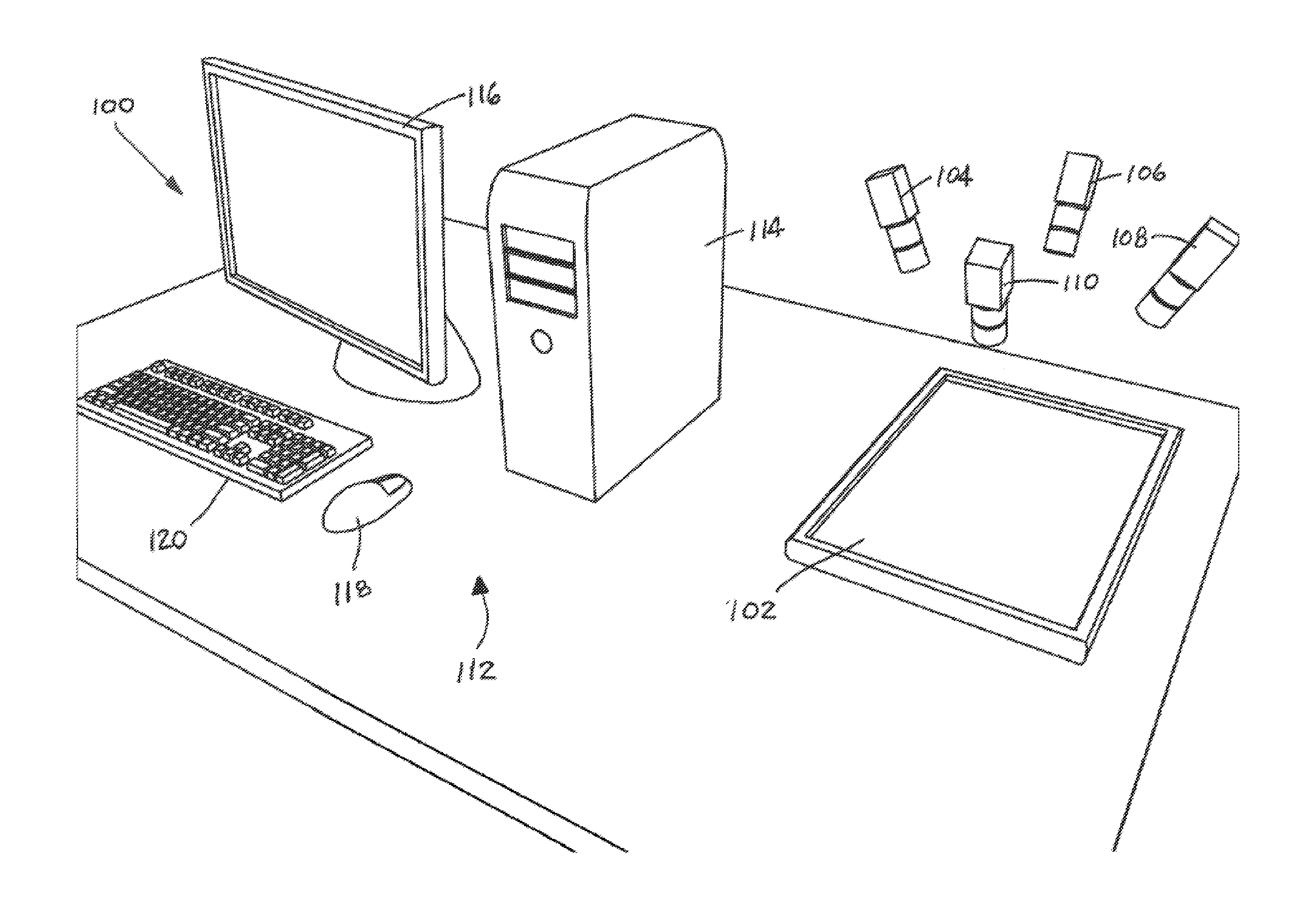
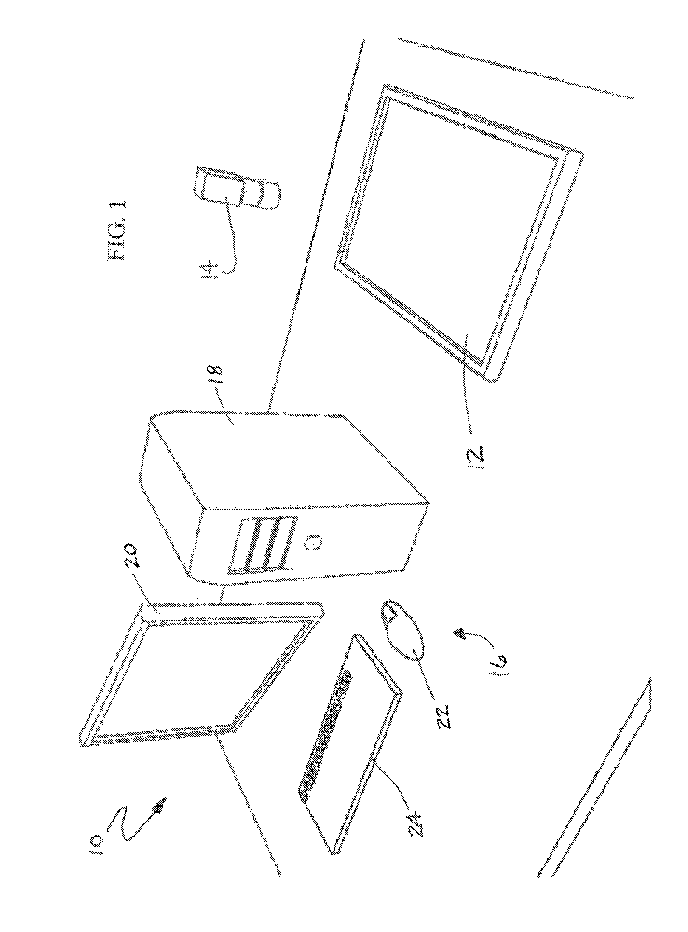
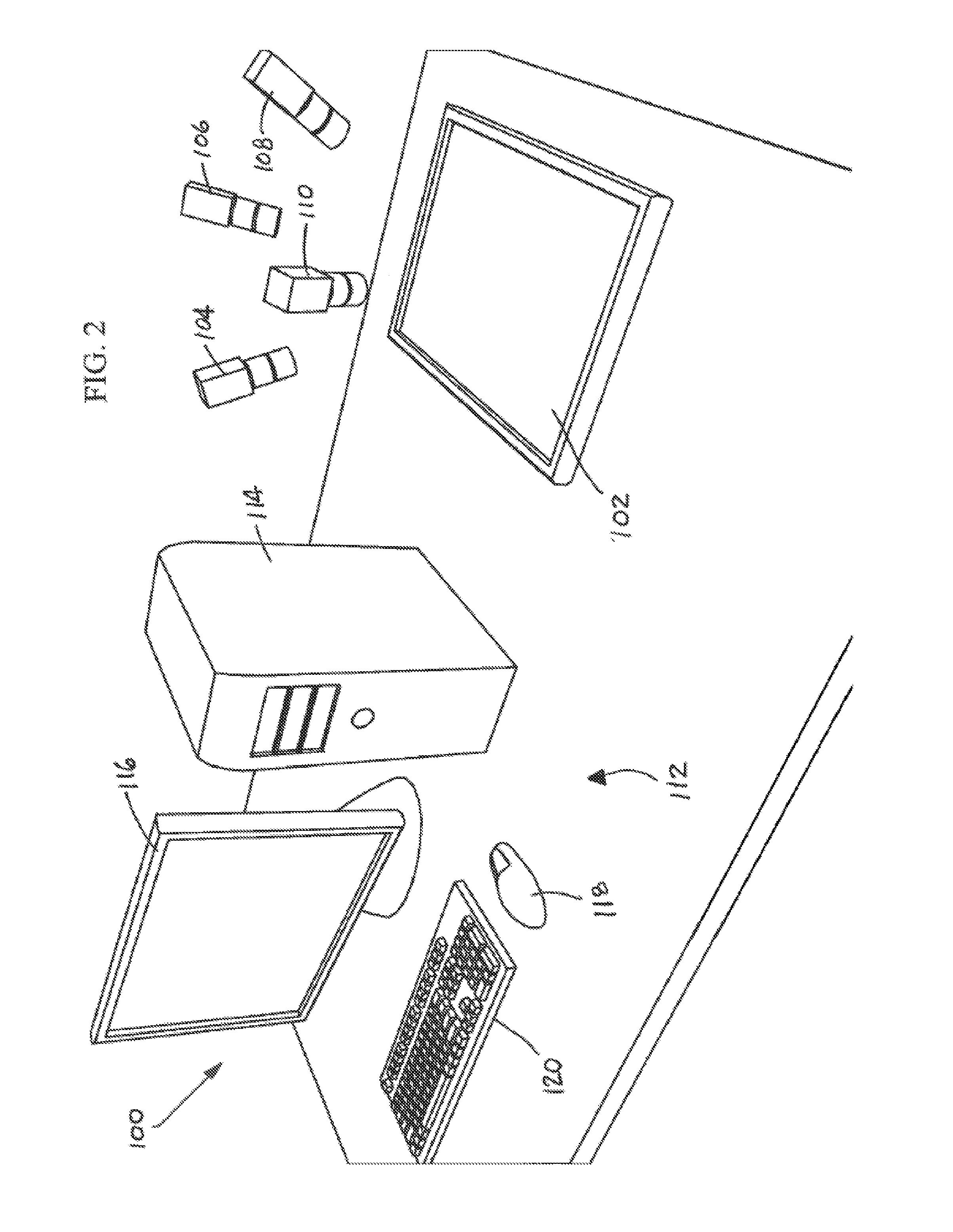
[0025]Reference is now made to FIG. 1 schematically illustrating a 3D workpiece imaging system 10 which may be broadly described as comprising a display screen 12 such as an LCD monitor, an imager 14 and a computing system 16. The imager 14 may be any suitable imager, such as a digital camera capable of converting image data to digital data for subsequent processing. The computing system 16 includes a computing devi...


PUM


Abstract

Methods and systems for three-dimensional virtual reconstruction of a workpiece surface are provided. A workpiece is positioned on a display screen between the display screen and at least one imager. The imager acquires multiple images of the workpiece while (a) multiple light stripes are displayed and swept in a first directional orientation across the display screen, (b) multiple light stripes are displayed and swept in at least one second directional orientation across the display screen, and (c) multiple images for each position of the multiple light stripes at different exposure times are captured. From the multiple images, a difference caused by the workpiece in a width and a profile of the multiple light stripes is determined. That difference is used to calculate a depth value (z) of the workpiece at each imager pixel position (x, y). The calculated depth value is used to reconstruct a surface shape of the workpiece. In embodiments, the described transmittance light capture analyses are supplemented with reflectance light capture analyses.

Description

[0001]This utility patent application claims the benefit of priority in U.S. Provisional Patent Application Ser. No. 61 / 823,468 filed on May 15, 2013, the entirety of the disclosure of which is incorporated herein by reference.TECHNICAL FIELD[0002]The present disclosure relates to human-computer interaction systems. More specifically, this disclosure pertains to methods and systems for three-dimensional (3D) imaging of workpieces allowing transmission of light therethrough. Automated methods are provided to remove non-linear distortions caused by deterioration of the workpieces by estimating an image pixel depth and therefrom a surface reconstruction of the workpiece. In embodiments, high-dynamic-range (HDR) structured-light scanning methods are used and a 2D Gaussian model for light transmission is estimated for each captured pixel of the workpiece image. A Principle Component Analysis is then used to estimate the photometric error and effectively restore the original illumination ...

Claims


Application Information

Patent Timeline
IPC IPC(8): G06T7/00H04N13/02
CPCH04N13/0282G06T7/0075G01B11/2527G06T7/55
Inventor LANDON, GEORGE V.
Owner EASTERN KENTUCKY UNIVERSITY
Learn More