
Double entry channel ladle bottom

a technology of ladle bottom and double entry, which is applied in the field of refractory articles, can solve the problems of molten metal and slag to mix, slag contamination from both floating and entrained slag, and difficulty in casting or refining operations, so as to reduce the amount of discarded metal, and minimize the effect of vortexing

Active Publication Date: 2014-11-20
VESUVIUS USA CORP
View PDF1 Cites 1 Cited by
  • Summary
  • Abstract
  • Description
  • Claims
  • Application Information

AI Technical Summary

Benefits of technology

The patent text describes a new ladle bottom configuration that reduces the problem of slag flow and contamination during metal draining. This results in a higher efficiency of the ladle drainage operation, with less waste and contamination in the metal effluent. The invention is about improving the design of the ladle bottom, specifically the outlet block, to increase the amount of liquid metal that can be drained without contamination by slag.

Problems solved by technology

Contamination is undesirable and may cause difficulties in casting or refining operations as well as defects in the intermediate or final metal products.
Slag contamination can occur from both floating and entrained slag.
Entrainment often occurs when turbulence disturbs the interface between molten metal and slag.
Such turbulence can cause molten metal and slag to mix.
Under quiescent conditions, entrained slag would eventually float to the surface; however, the turbulence of casting can maintain a substantial amount of entrained slag in the molten metal.
As the metal drains from the ladle, the floating slag approaches the outlet and the likelihood of contamination of the metal stream by slag increases.
The operator may even stop the pour prematurely to avoid slag in the ladle outflow.
Discarding metal decreases yield, which is costly and inefficient but, at the same time, is necessary to reduce slag contamination.
Both techniques only detect the presence of slag and do not actively decrease the presence of slag in the outflow.
However, this configuration has not been optimized for vortexing reduction.

Method used


Image

  • Double entry channel ladle bottom
  • Double entry channel ladle bottom
  • Double entry channel ladle bottom

Examples


Embodiment Construction

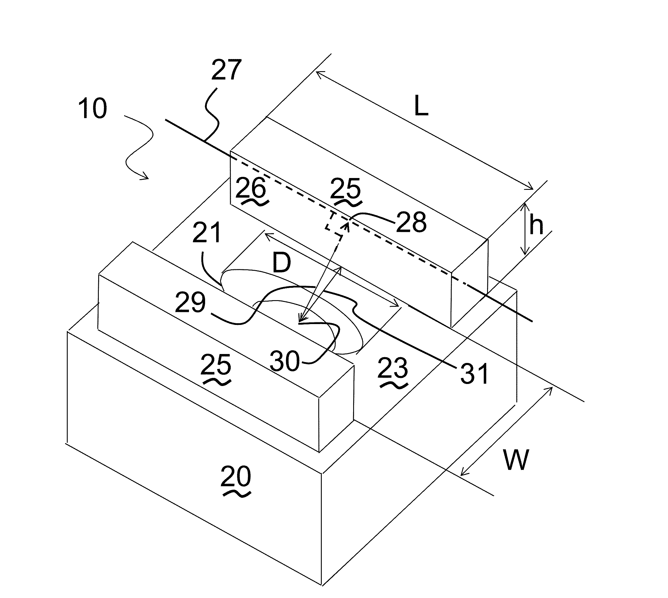
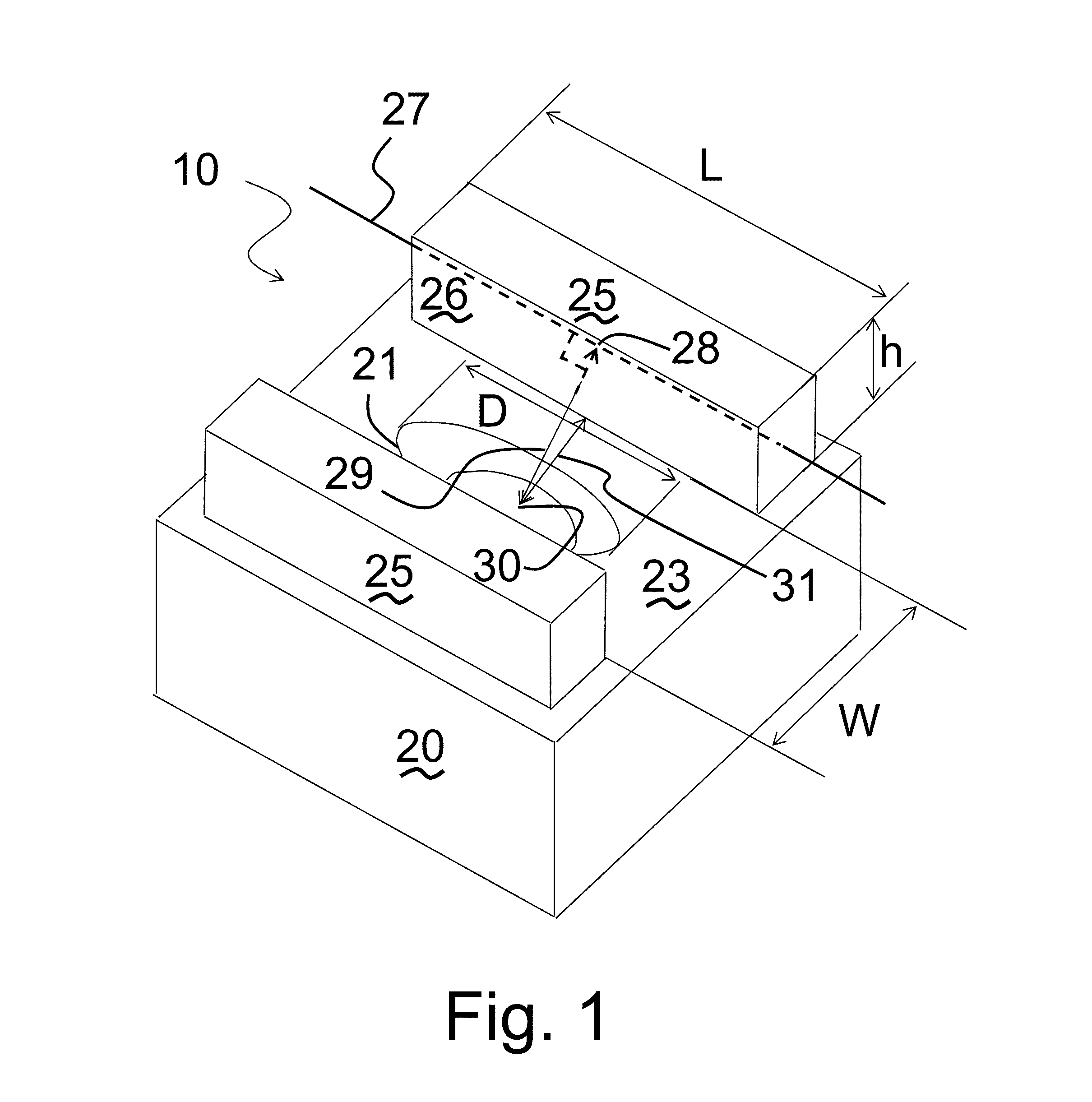
[0034]FIG. 1 shows one embodiment of a ladle block 10 of the present invention. The ladle block 10 contains a ladle block body 20, through which an outlet bore 21 passes downwardly from a ladle block body upper surface 23. Walls 25 extend upwardly from ladle block body 20. Walls 25 are disposed on opposite sides of outlet bore 21. Walls 25 are separated by an outlet channel having a width of W. Walls 25 have a height denoted by h. Walls 25 have a length denoted by L. Outlet bore 21 has a main dimension denoted by D. Wall interior surface 26 is the portion of wall 25 facing the volume above outlet bore 21.

[0035]Outlet bore 21 may have an entrance in ladle block body upper surface 23 in the shape of a circle or in the shape of an oval. The entrance of outlet bore 21 may be circular, or may describe an oval. The main dimension D of outlet bore 21 may be parallel to the length L of walls 25. The surface of outlet bore 21 descending from ladle block body upper surface 23 may include a fr...


PUM

PropertyMeasurementUnit
Angleaaaaaaaaaa
Angleaaaaaaaaaa
Angleaaaaaaaaaa

Abstract

A metallurgical ladle, and more particularly the bottom of the ladle or a ladle block in the bottom of the ladle, have an outlet through which the molten metal can drain. The ladle bottom contains an open-end channel bounded by at least one wall with a major dimension perpendicular to a line joining the center of the outlet entrance to the center of the wall. In selected configurations, opposing faces of the walls bounding the open-end channel are convex in the horizontal plane and concave in the horizontal plane, respectively.

Description

BACKGROUND OF THE INVENTION[0001](1) Field of the Invention[0002]This invention relates generally to refractory articles and, more particularly, to a refractory shape used in the transfer of molten metal in a continuous casting operation.[0003](2) Description of Related Art including information disclosed under 37 CFR 1.97 and 1.98.[0004]A ladle is a vessel that is used to hold or transport a batch of liquid metal during metallurgical operations. A layer of slag frequently covers the top surface of the liquid metal, such as in the production of steel. When desired, the liquid metal may be drained from the ladle though an outlet located in the ladle bottom. While draining, the metal will, desirably and advantageously, completely empty from the ladle without contamination of the metal by slag. Contamination is undesirable and may cause difficulties in casting or refining operations as well as defects in the intermediate or final metal products.[0005]Slag contamination can occur from b...

Claims


Application Information

Patent Timeline
IPC IPC(8): B22D41/08
CPCB22D41/08B22D43/001Y02P10/20
Inventor RICHAUD, JOHANCHUNG, WILLIAM
Owner VESUVIUS USA CORP
Learn More