Device For Locking To A DIN Rail

a technology of din rail and device, which is applied in the direction of electrical apparatus construction details, applications, show stands, etc., can solve the problems of prone to faults, difficult installation, and overly complicated mechanisms, and achieve the effect of effective engagement of the device with the din rail, convenient attachment of electrical equipment, and easy rotation of the sha

Active Publication Date: 2014-11-20
NIDEC CONTROL TECHN LTD
View PDF17 Cites 1 Cited by
  • Summary
  • Abstract
  • Description
  • Claims
  • Application Information

AI Technical Summary

Benefits of technology

[0018]In some embodiments, each rail-contacting portion may have a similar dimension to an outwardly protruding flange of the DIN rail. Thus, in combination with the clamping force exerted by the stopping portions on the side of the DIN rail, a more effective engagement of the device with the DIN rail may be enabled.
[0019]The device may be coupled to or with a platform capable of supporting a component mounted thereto. The platform may have dimensions in the region of 95 mm×25 mm×12 mm, though these are of course merely exemplary. The shaft may be arranged to rotate relative to the platform. Thus, the platform may provide a base for allowing relative moveme

Problems solved by technology

However, such mechanisms have the tendency to be overly complicated and burdensome.
As a result, they can be prone to fau

Method used


Image

  • Device For Locking To A DIN Rail
  • Device For Locking To A DIN Rail
  • Device For Locking To A DIN Rail

Examples


Embodiment Construction

[0051]The present invention seeks to provide an improved device for locking to a DIN rail. Whilst various embodiments of the invention are described below, the invention is not limited to these embodiments, and variations of these embodiments may well fall within the scope of the invention which is to be limited only by the appended claims.

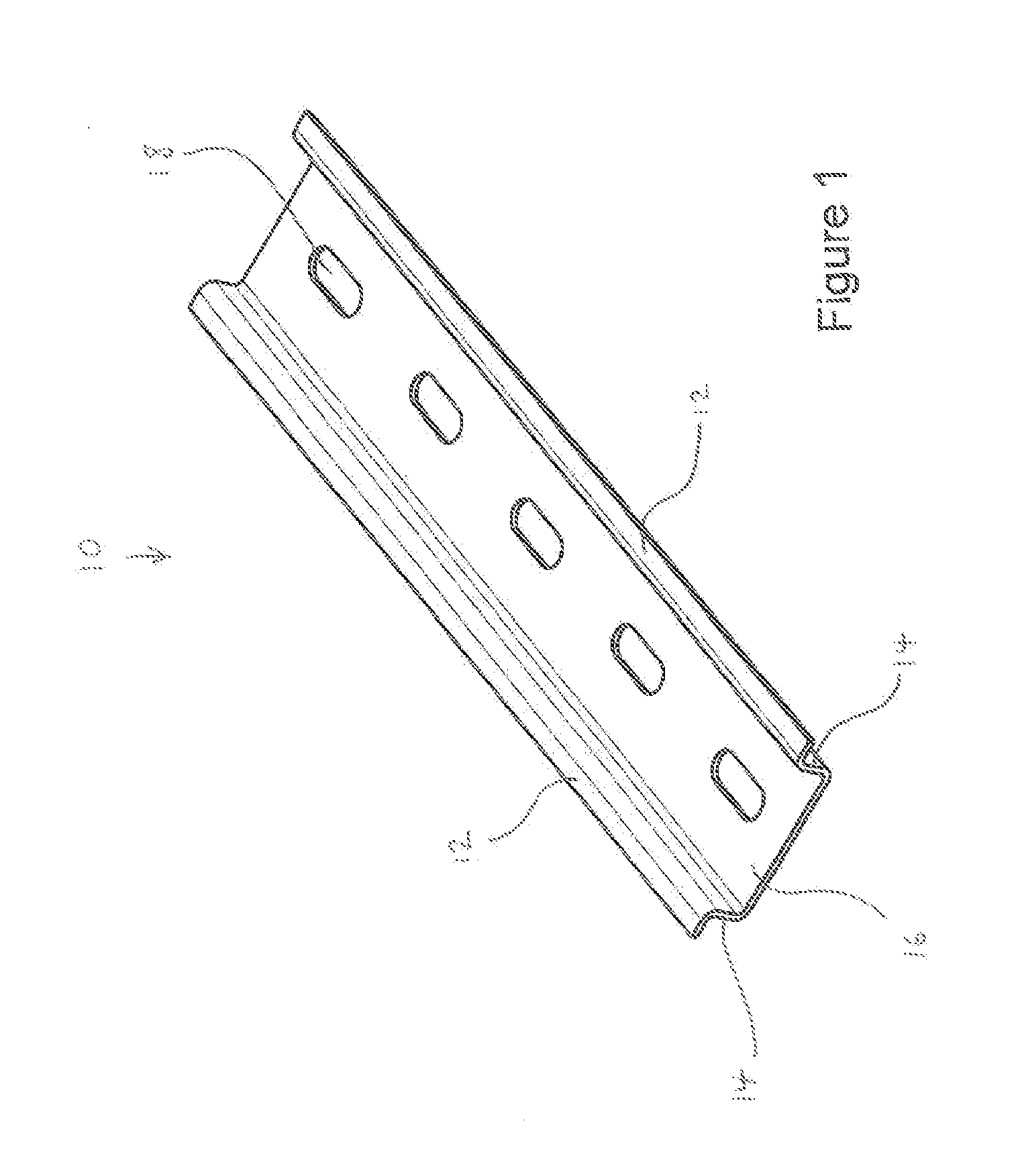
[0052]FIG. 1 shows a typical DIN rail 10. DIN rail 10 has a hat-shaped cross-section characterised by two outwardly protruding flanges 12, joined at right angles to two vertical upright portions 14. Upright portions 14 are connected by top portion 16 with apertures 18 formed therein. Apertures 18 may be used to affix DIN rail 10 to a wall or ceiling, for example. The exact dimensions of DIN rail 10 may vary. In addition, other types of DIN rails with different cross-sections (such as a C-section or a G-section) may be used with the present invention.

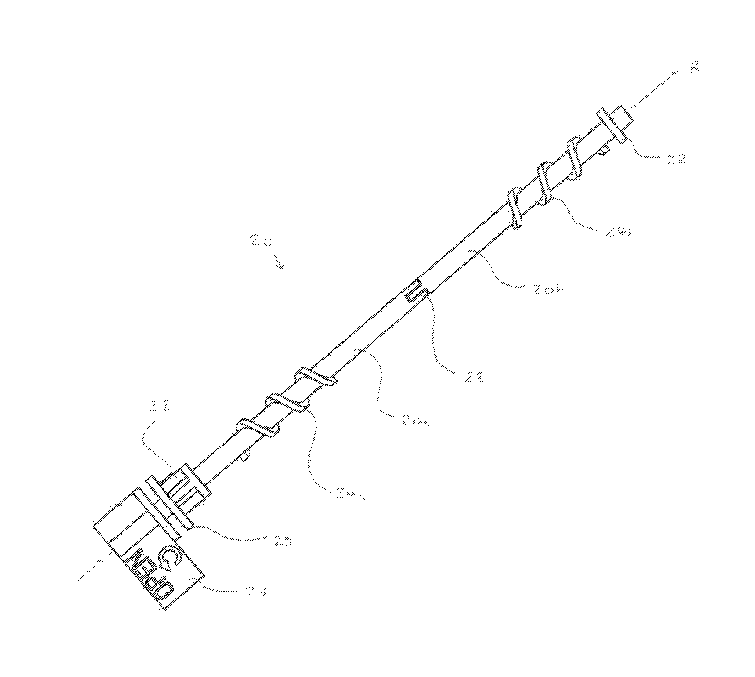
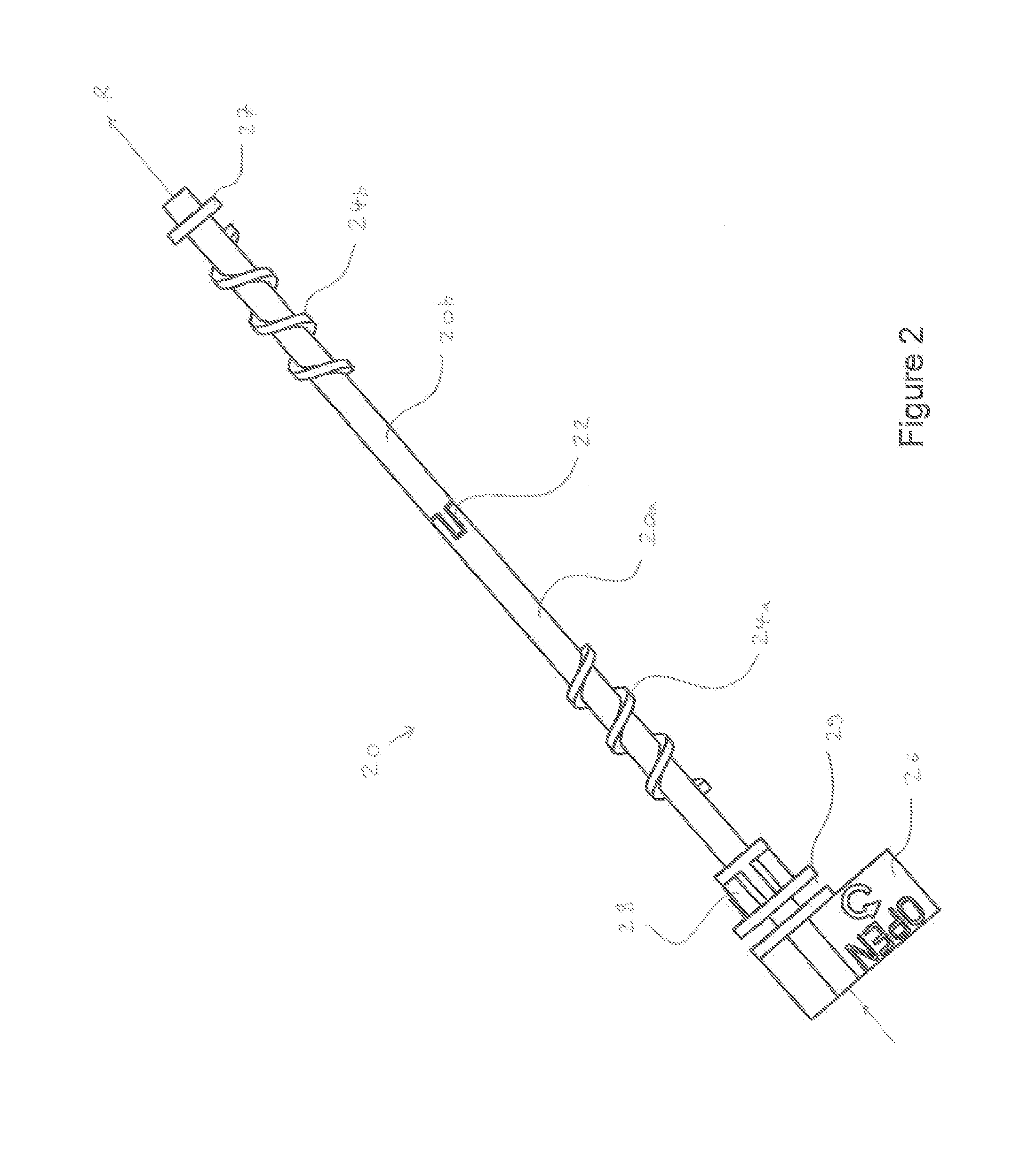
[0053]FIG. 2 shows a shaft 20 according to a preferred embodiment of the present invention. Shaft 2...


PUM


Abstract

There is provided a device (50) for locking to a DIN rail (10). The device comprises a shaft (20) defining an axis of rotation, and first and second rail-engaging members (30a, 30b) connected to the shaft. The rail-engaging members are each shaped to engage a DIN rail in a respective engaging position. The shaft is rotatable about the axis of rotation and thereby arranged to urge each rail-engaging member into its respective engaging position with a DIN rail positioned between the first and second rail-engaging members. The invention provides for a means of locking a device to a DIN rail. Once locked to the DIN rail, an electrical component such as a circuit breaker or the like may be mounted or coupled to the device. The locking device may provide for rapid removal/attachment to the DIN rail. Equipment may either be mounted directly to the locking device or indirectly by mounting the component or electrical equipment to a platform or other support that is itself attached to the locking device. There is also provided a method of mounting a component (60) to a DIN rail (10). The method comprises positioning the DIN rail between first and second rail-engaging members (30a, 30b) connected to an actuator (20). The method further comprises triggering the actuator so as to simultaneously urge each rail-engaging member into engagement with the DIN rail. The method further comprises mounting the component to the actuator and/or at least one of the rail-engaging members. There is also provided a method of forming a device (50) for locking to a DIN rail (10). The method comprises threading a first rail-engaging member (30b) onto a first threaded shaft portion (20b). The method also comprises threading a second rail-engaging member (30a) onto a second threaded shaft portion (20a). The method also comprises joining the first and second shaft portions.

Description

CROSS-REFERENCE TO RELATED APPLICATION[0001]This application claims the benefit and priority of Great Britain Patent Application No. 1308809.1 filed May 16, 2013. The entire disclosure of the above application is incorporated herein by reference.FIELD OF THE INVENTION[0002]The present invention relates to a device for locking to a DIN rail, and in particular to a device capable of being locked or clamped to a DIN rail so that electrical devices or components may be mounted to the DIN rail.BACKGROUND TO THE INVENTION[0003]DIN rails are standard metal pressings used for mounting industrial control equipment, such as connectors, switches, machine controllers, and circuit breakers. They come in various standardised shapes and can be cut to a desired length in accordance with the environment in which they will be installed. A DIN rail may be attached to a ceiling, or inside a cabinet, for example, so that electrical components may be attached, hung or suspended therefrom. Alternatively, ...

Claims


Application Information

Patent Timeline
IPC IPC(8): H05K7/18H05K7/12H05K7/02
CPCH05K7/183H05K7/12H05K7/026H05K7/02H02B1/0523H02B1/0526Y10T29/49826
Inventor CACHIA, CHARLES ANTHONY
Owner NIDEC CONTROL TECHN LTD
Why Eureka
Try Eureka