
Simple automatic electronic tourniquet

a technology of electronic tourniquet and automatic operation, which is applied in the field of simple automatic electronic tourniquet, can solve the problems of pain in the arm on occasion, difficulty in constricting the arm with appropriate tourniquet pressure, and weak or too strong constricting strength, so as to reduce the pressure of the wrapping member, and reduce the time required for performing tourniquet.

Active Publication Date: 2014-11-13
MASAKI NOBUYUKI
View PDF9 Cites 18 Cited by
  • Summary
  • Abstract
  • Description
  • Claims
  • Application Information

AI Technical Summary

Benefits of technology

This patent is about a device that detects changes in a person's blood pressure during a tourniquet procedure. It uses a circuit to control the pressure of a wrapping member that is placed around the person's body part where the blood sample is to be taken. This device ensures that the pressures applied to the person's body are within acceptable limits, so they are not damaged during the procedure. It also reduces the time needed for the tourniquet to be applied, as it detects changes in blood pressure and adjusts the pressure of the wrapping member accordingly. Overall, this device provides an improved and safer method for controlling blood pressure during a tourniquet procedure.

Problems solved by technology

Therefore, constricting strength is either too weak or too strong, and it is difficult to constrict the arm with appropriate tourniquet pressures.
However, when the systolic blood pressure is detected with using the above-mentioned tourniquet, as the arm must be pressed in a pressure well beyond the systolic blood pressure, a problem is that pain is felt in the arm on the occasion.
Therefore, another problem is that much time is needed in the preparatory stage before venipuncture.

Method used


Image

  • Simple automatic electronic tourniquet
  • Simple automatic electronic tourniquet
  • Simple automatic electronic tourniquet

Examples


embodiment 1

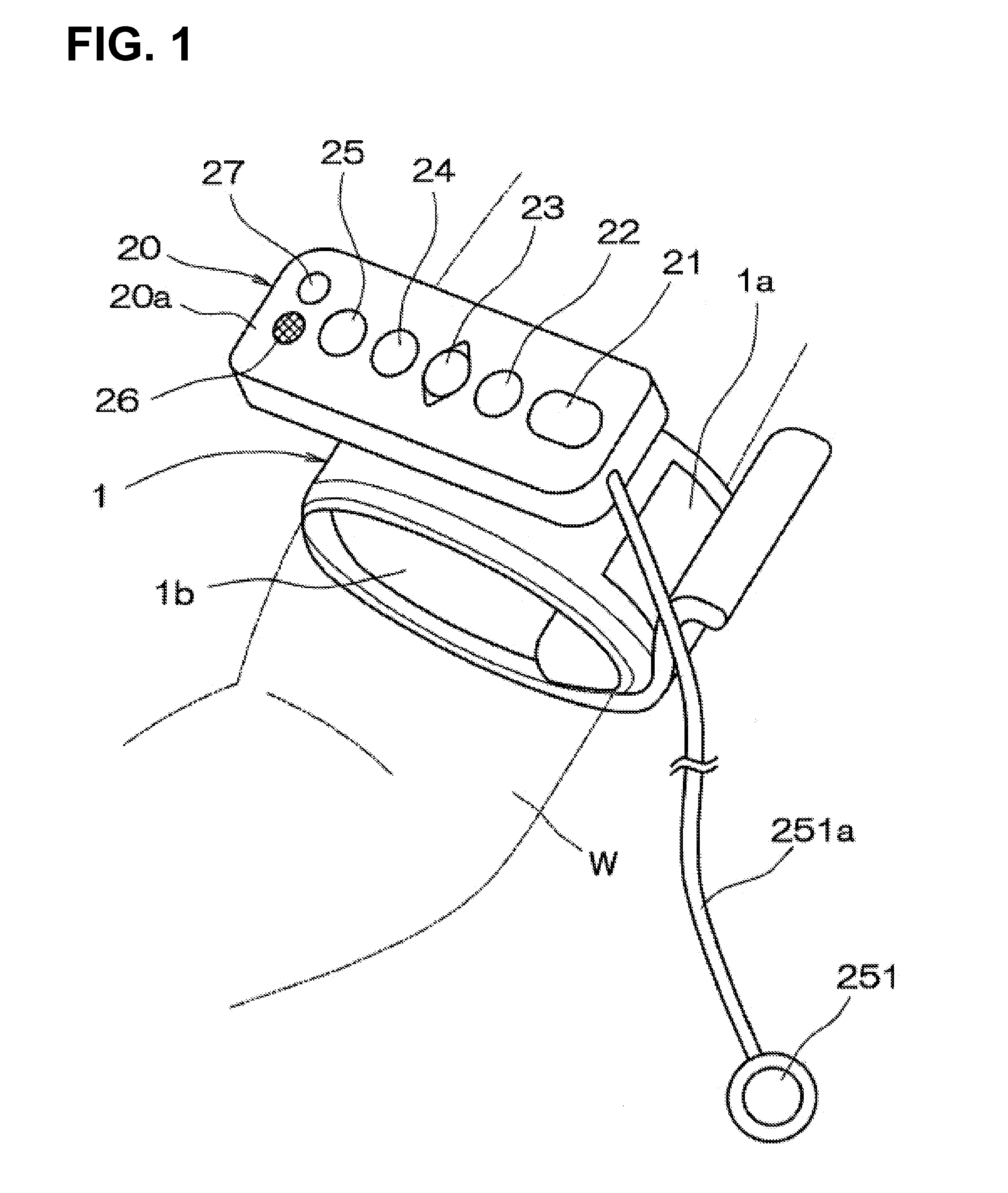
[0045]The first embodiment of the present invention for a simple automatic electronic tourniquet of the present invention as shown in FIGS. 1 and 2 comprises a manchette (wrapping member) 1 mounted so as to be wrapped around the upper arm W, one of the extremities of the human body, and a controller 2 integrally provided on the manchette 1.

[0046]When wrapped around the upper arm W, the manchette 1 is maintained in a roll-like shape by a surface-formed fastener part 1a, and is either attachable to or detachable from the upper arm W easily.

[0047]Also, the manchette 1 comprises a pressurized bag 1b at its inner surface when rolled for applying pressure to the upper arm W.

[0048]At a portion of either the manchette 1 or the pressurized bag 1b which contacts with the upper arm W, a biological signal detecting sensor 1c (cf. FIG. 2) for detecting the biological signal such as Korotkov's sound which either develops or disappears depending on the condition of intra-arterial blood flow.

[0049]...

embodiment 2

[0093]Then, the second embodiment of the present invention is described with reference to FIGS. 3 and 4. However, the same code is referred to elements common to the elements of the first embodiment shown in FIGS. 1 and 2, and explanations thereon are omitted.

[0094]The difference between the second embodiment of the simple automatic electronic tourniquet and the first embodiment is that a small display 28A is provided as informing means besides the speaker 26, that a fixed throttle (fixed flow control valve) 305a is provided on the directional control valve 305, and that an exhaust directional control valve 310 for letting air out of the pressurized bag 1b rapidly.

[0095]That is, as shown in FIG. 4, when the directional control valve 305 is in the neutral position, the P port is not communicated with the A port, and the R port is communicated with the B port. The fixed throttle 305a is arranged between them. When switched, the P port is communicated with the A port, and the R port is...

embodiment 3

[0102]Then, the third embodiment of the present invention is described with reference to FIGS. 5 and 6. However, the same code is referred to elements common to the elements of the second embodiment shown in FIGS. 3 and 4, and explanations thereon are omitted.

[0103]The difference between the third embodiment of the simple automatic electronic tourniquet and the second embodiment is that a large display 28B is provided as informing means, that the fixed throttle 305a is removed in the directional control valve 305, and that a variable throttle (variable flow regulating valve) 313 is provided between the pressurized bag 1b and the B port of the directional control valve 305.

[0104]Since the fixed throttle 305a is removed from the directional control valve 305, the R port is simply communicated with the R port in the neutral position. The variable throttle 313 can adjust, by a rotary knob 313a, rate of flow of the air discharged from the pressurized bag 1b to the atmosphere through the ...


PUM


Abstract

The present invention provides a simple auto electronic tourniquet which does not inflict pain on a person receiving tourniquet in the preparatory stage before venipuncture and which shorten the time required in preparation for venipuncture. The simple auto electronic tourniquet includes a manchette (wrapping member) wrapped around the upper arm and a controller provided on the manchette for controlling pressures to the upper arm by the wrapping member. The controller includes a diastolic blood pressure detecting circuit and a pressure setting and maintenance circuit The pressure setting and maintenance circuit setting pressures of the manchette at the time when changes of the biological signal are detected by the diastolic blood pressure detecting circuit as target pressures.

Description

FIELD OF THE INVENTION[0001]The present invention relates to a simple auto electronic tourniquet which can appropriately and easily perform venipuncture, drawing blood, securing of vein root (vascular security) and so on.BACKGROUND ART[0002]Tourniquet is usually performed in the sites such as the drawing blood by, for example, winding an elastic band around the arm of human body. However, nurses and so on conventionally depend on their own sense and decide constricting strength of the rubber band by themselves. Therefore, constricting strength is either too weak or too strong, and it is difficult to constrict the arm with appropriate tourniquet pressures. Therefore, the development of the simple auto electronic tourniquet which can automatically constrict the arm with appropriate tourniquet pressures has been expected.[0003]On the other hand, as a tourniquet which could automatically perform tourniquet to some extent, the one has been known which comprises a manchette mountable to t...

Claims


Application Information

Patent Timeline
Patent Type & Authority Applications(United States)
IPC IPC(8): A61B17/135
CPCA61B17/1355A61B17/135A61B5/02233A61B5/0225A61B5/6843A61M5/1723A61M5/42A61B17/132A61B17/1322
Inventor MASAKI, NOBUYUKI
Owner MASAKI NOBUYUKI
Learn More